Functions
6-180
7SA6 Manual
C53000-G1176-C156-2
6.13
Earth Fault Detection in Non-Earthed Systems
6.13.1 Method of Operation
General
In systems whose starpoint is either non-earthed or earthed through an arc suppres-
sion coil (Petersen coil), single phase earth faults will not be detected by the short cir-
cuit protection, since no significant earth fault current flows. Furthermore, since net-
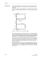
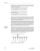
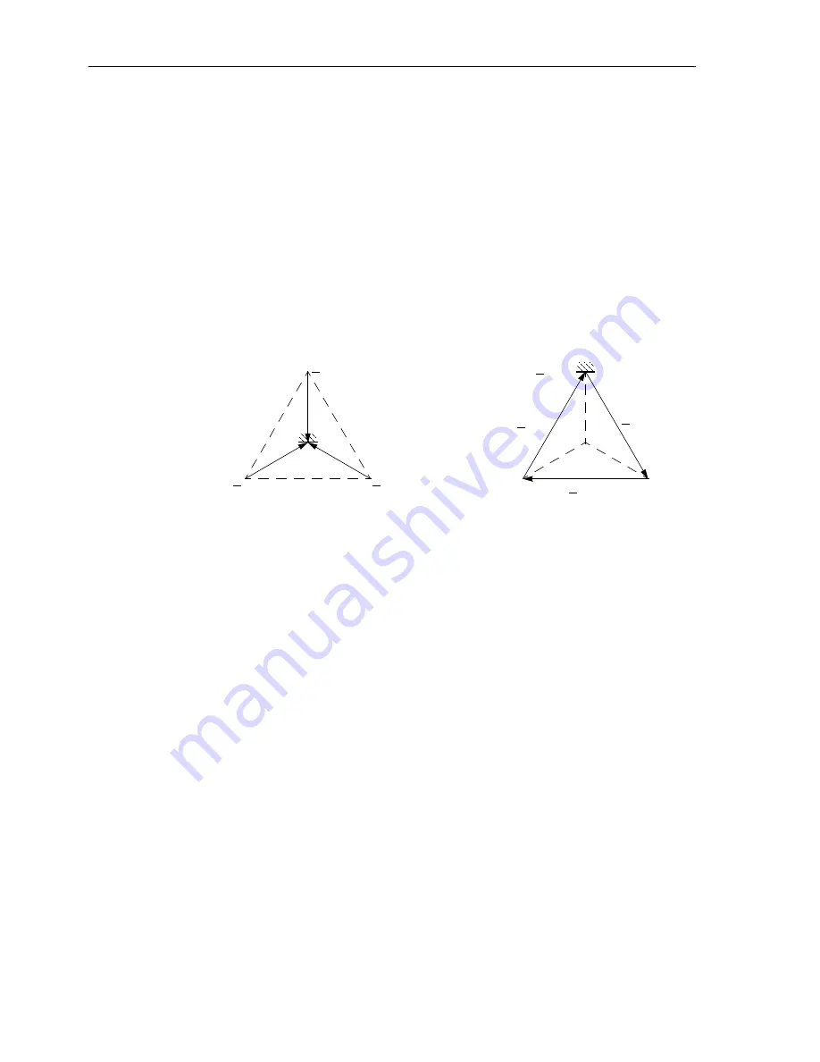
work operation is not immediately affected by an earth fault (the voltage triangle is
maintained, Figure 6-96) rapid disconnection is not normally desired. It is more impor-
tant that the earth fault be recognized, indicated and, when possible, localized also.
After network reconfiguration it can then be cleared. But 7SA6 enables the user to trip
on directional earth fault in non-earthed systems.
Figure 6-96
Earth fault in non-earthed neutral network
Dependent upon the chosen model, a 7SA6 relay can be fitted with optional earth fault
detection module, which includes the following functions:
•
Detection of an earth fault (pick-up) by monitoring the displacement voltage,
•
Determination of the faulted phase by measuring the phase to earth voltages,
•
Determination of the direction of the earth fault (residual) current by high accuracy
real and reactive component measurement.
Pickup
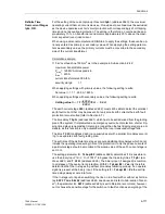
The pickup is achieved when the settable threshold for the displacement voltage 3
⋅
U
0
is exceeded. To ensure measurement of stable values, all earth fault detection func-
tions are delayed until 1 second (settable) after inception of voltage displacement. Fur-
ther, each alteration of the earth fault conditions (e.g. altered direction) is recognized
only after this delay. Generally the pickup is only indicated if a fault was detected for
sure by the phase determination function (see next margin heading).
Determination of
the Earth-faulted
Phase
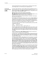
After recognition of displaced voltage conditions the first objective of the device is se-
lective detection of the earth-faulted phase. For this purpose the individual phase-to-
earth voltages are measured. The affected phase is the one in which the voltage is
below the settable threshold
Uph-e min
when simultaneously the other two voltages
exceed an equally settable maximum threshold
Uph-e max
.
E
U
L1
U
L2
U
L3
E
U
L1
= 0
U
L3–L1
U
L1–L2
U
L2–L3
b) Earth fault in phase L1
a) Healthy network, without earth fault
Summary of Contents for siprotec 7SA6
Page 2: ...Siemens Aktiengesellschaft Book No C53000 G1176 C156 2 ...
Page 18: ...xviii 7SA6 Manual C53000 G1176 C156 2 ...
Page 32: ...Introduction 1 14 7SA6 Manual C53000 G1176 C156 2 ...
Page 82: ...Hardware and Connections 2 50 7SA6 Manual C53000 G1176 C156 2 ...
Page 119: ...SIPROTEC 4 Devices 4 25 7SA6 Manual C53000 G1176 C156 2 Figure 4 20 CFC Logic example ...
Page 190: ...Configuration 5 62 7SA6 Manual C53000 G1176 C156 2 ...
Page 652: ...Installation and Commissioning 8 78 7SA6 Manual C53000 G1176 C156 2 ...
Page 724: ...Technical Data 10 56 7SA6 Manual C53000 G1176 C156 ...
Page 800: ...Appendix A 76 7SA6 Manual C53000 G1176 C156 2 ...
Page 866: ...Appendix B 66 7SA6 Manual C53000 G1176 C156 2 ...

