Functions
6-193
7SA6 Manual
C53000-G1176-C156-2
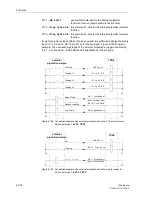
binary inputs (“
>CB1 Pole L1
”, F.No.
366
, “
>CB1 Pole L2
”, F.No.
367
and
“
>CB1 Pole L3
”, F.No.
368
) for each pole.
If in stead of the individual pole auxiliary contacts, the series connection of the normal-
ly open and normally closed contacts are used (the normal state applies when the CB
is open), the CB is assumed to have all three poles open when the series connection
of the normally closed contacts is closed (binary input “
>CB1 3p Open
”, F.No.
411
).
It has all three poles closed when the series connection of the normally open contacts
is closed (binary input “
>CB1 3p Closed
”, F.No.
410
). If neither of these conditions
are present, it is assumed that the circuit breaker has one pole open (even if this con-
dition also theoretically applies to the two-pole open state).
The device continuously checks the switching state of the circuit-breaker: As long as
the auxiliary contacts indicate that the CB is not closed (three-pole), the automatic re-
closure function cannot be started. This guarantees that a close command can only
be issued if the CB was previously tripped (out of the closed state).
The valid dead time starts when the trip command resets or when the auxiliary con-
tacts indicate that the CB (pole) has opened.
If the CB opens with three-pole reclose cycles after a single pole trip command, this is
considered as a three-pole trip. If three-pole reclose cycles are allowed, the dead time
for three-pole tripping is activated with the operating mode: control by trip command
(see above under title “Operating Modes of the Automatic Reclosure Function”, page
191); with the mode: control by starting, the type of fault indicated by the protection
function(s) issuing the start is still valid. If three-pole reclose cycles are not allowed,
reclosure is blocked dynamically. The trip command is final.
The latter also applies if the CB trips two poles following a single-pole trip command.
The device can only detect this if the auxiliary contacts of each pole are connected in-
dividually. The device immediately initiates three-pole coupling thus resulting in a
three-pole trip command.
If the CB auxiliary contacts indicate that at least one further pole has opened during
the dead time following a single-pole trip, a three-pole reclose cycle is initiated with the
dead time for three-pole reclosure if this is allowed. If the auxiliary contacts are con-
nected for each pole individually, the device can detect the two-pole open state of a
CB. In this case the device immediately issues a three-pole trip command provided
that the forced three-pole coupling is activated (see section 6.14.2 and refer to “Forced
Three-pole Trip”, page 207).
Sequence of a
Three-pole
Reclose Cycle
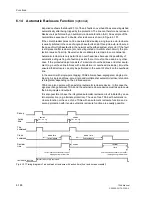
If the automatic reclosure function is ready, the short-circuit protection trips three pole
for all faults inside the stage valid for reclosure. The automatic reclosure function is
then started. When the trip command resets or the circuit-breaker opens (auxiliary
contact criterion) an (adjustable) dead time starts. At the end of this dead time the cir-
cuit-breaker receives a close command. At the same time the (adjustable) reclaim
time is started. If
AR control mode
was set under address
134
with Pickup
dur-
ing configuration of the protective functions, different dead times can be parameter-
ized depending on the type of fault recognised by the protection.
If the fault is cleared (successful reclosure), the reclaim time runs out and all functions
return to their quiescent state. The system fault has ended.
If the fault is not cleared (unsuccessful reclosure), the short-circuit protection issues a
final trip with the protection stage that is selected to operate without reclosure. Any
fault during the reclaim time leads to a final trip.
After unsuccessful reclosure (final tripping), the automatic reclosure is blocked dy-
namically (see also page 191, “Reclose Block”).
Summary of Contents for siprotec 7SA6
Page 2: ...Siemens Aktiengesellschaft Book No C53000 G1176 C156 2 ...
Page 18: ...xviii 7SA6 Manual C53000 G1176 C156 2 ...
Page 32: ...Introduction 1 14 7SA6 Manual C53000 G1176 C156 2 ...
Page 82: ...Hardware and Connections 2 50 7SA6 Manual C53000 G1176 C156 2 ...
Page 119: ...SIPROTEC 4 Devices 4 25 7SA6 Manual C53000 G1176 C156 2 Figure 4 20 CFC Logic example ...
Page 190: ...Configuration 5 62 7SA6 Manual C53000 G1176 C156 2 ...
Page 652: ...Installation and Commissioning 8 78 7SA6 Manual C53000 G1176 C156 2 ...
Page 724: ...Technical Data 10 56 7SA6 Manual C53000 G1176 C156 ...
Page 800: ...Appendix A 76 7SA6 Manual C53000 G1176 C156 2 ...
Page 866: ...Appendix B 66 7SA6 Manual C53000 G1176 C156 2 ...

