Functions
6-231
7SA6 Manual
C53000-G1176-C156-2
6.16.1.2 Undervoltage Protection
Undervoltage
Phase–Earth
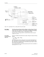
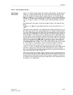
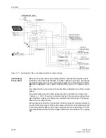
Figure 6-117 depicts the logic diagram of the phase voltage stages. The fundamental
frequency is numerically filtered from each of the three measuring voltages so that
harmonics or transient voltage peaks are largely harmless. Two threshold stages
Uph-e<
and
Uph-e<<
are compared with the voltages. If phase voltage falls below
a threshold it is indicated phase-segregated. Furthermore, a general pick-up indication
“
Uph-e< Pickup
” or “
Uph-e<< Pickup
” is given. The drop-off to pick-up ratio is
1.05.
Each stage starts a time delay common to all phases. Expiry of the respective time
delay
T Uph-e<
or
T Uph-e<<
is signalled and results in the trip command “
Uph-e<(<)
TRIP
”.
Depending on the configuration of the substations the voltage transformers are locat-
ed on the busbar side or on the outgoing feeder side. This results in a different behav-
iour of the undervoltage protection when the line is deenergized. While the voltage re-
mains present or reappears at the busbar side after a trip command and opening of
the circuit breaker, it is switched on at the outgoing side. For the undervoltage protec-
tion this results in a pick-up state being present if the voltage transformers are on the
outgoing side. If this pick-up must be reset, the current can be used as an additional
criterion (current supervision
CURR.SUP.
) to achieve this result. Undervoltage will
then only be detected if, together with the undervoltage condition, the minimum cur-
rent
PoleOpenCurrent
(address
1130
) of the corresponding phase is also exceed-
ed. This condition is communicated by the central function control of the device.
The undervoltage protection phase–earth can be blocked via the binary input
“
>Uph-e<(<) BLK
”. The stages of the undervoltage protection are then automatically
blocked if a voltage failure is detected (“Fuse–Failure–Monitor”, also see Section
6.21.1.3) or if the trip of the mcb of the voltage transformers is indicated (internal block-
ing) via the binary input “
>FAIL:Feeder VT
”.
Also during a single-pole automatic reclose dead time (using the internal autoreclos-
ure function) the stages of the undervoltage protection are automatically blocked in the
pole open state. If necessary, the current criterion will be considered, so that they do
not respond to the undervoltage of the disconnected phase when voltage transformers
are located on the outgoing side.
Summary of Contents for siprotec 7SA6
Page 2: ...Siemens Aktiengesellschaft Book No C53000 G1176 C156 2 ...
Page 18: ...xviii 7SA6 Manual C53000 G1176 C156 2 ...
Page 32: ...Introduction 1 14 7SA6 Manual C53000 G1176 C156 2 ...
Page 82: ...Hardware and Connections 2 50 7SA6 Manual C53000 G1176 C156 2 ...
Page 119: ...SIPROTEC 4 Devices 4 25 7SA6 Manual C53000 G1176 C156 2 Figure 4 20 CFC Logic example ...
Page 190: ...Configuration 5 62 7SA6 Manual C53000 G1176 C156 2 ...
Page 652: ...Installation and Commissioning 8 78 7SA6 Manual C53000 G1176 C156 2 ...
Page 724: ...Technical Data 10 56 7SA6 Manual C53000 G1176 C156 ...
Page 800: ...Appendix A 76 7SA6 Manual C53000 G1176 C156 2 ...
Page 866: ...Appendix B 66 7SA6 Manual C53000 G1176 C156 2 ...

