Functions
6-256
7SA6 Manual
C53000-G1176-C156-2
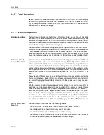
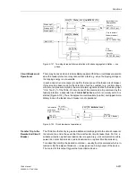
Different delay timers are provided for operation after common phase initiation and
phase segregated initiation. A third time stage can be used for two-stage breaker fail-
ure protection.
With single-stage breaker failure protection, the trip command is routed to the adjacent
circuit breakers should the local feeder breaker fail (refer to Figure 6-120 or 6-121).
The adjacent circuit breakers are all those which must trip in order to interrupt the fault
current, i.e. the breakers which feed the bus-bar or the bus-bar section to which the
feeder under consideration is connected. The possible initiation conditions for the
breaker failure protection are those discussed above. Depending on the application of
the feeder protection, common phase or phase segregated initiation conditions may
occur. Tripping by the breaker failure protection is always three-pole.
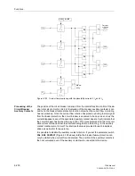
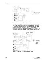
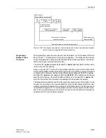
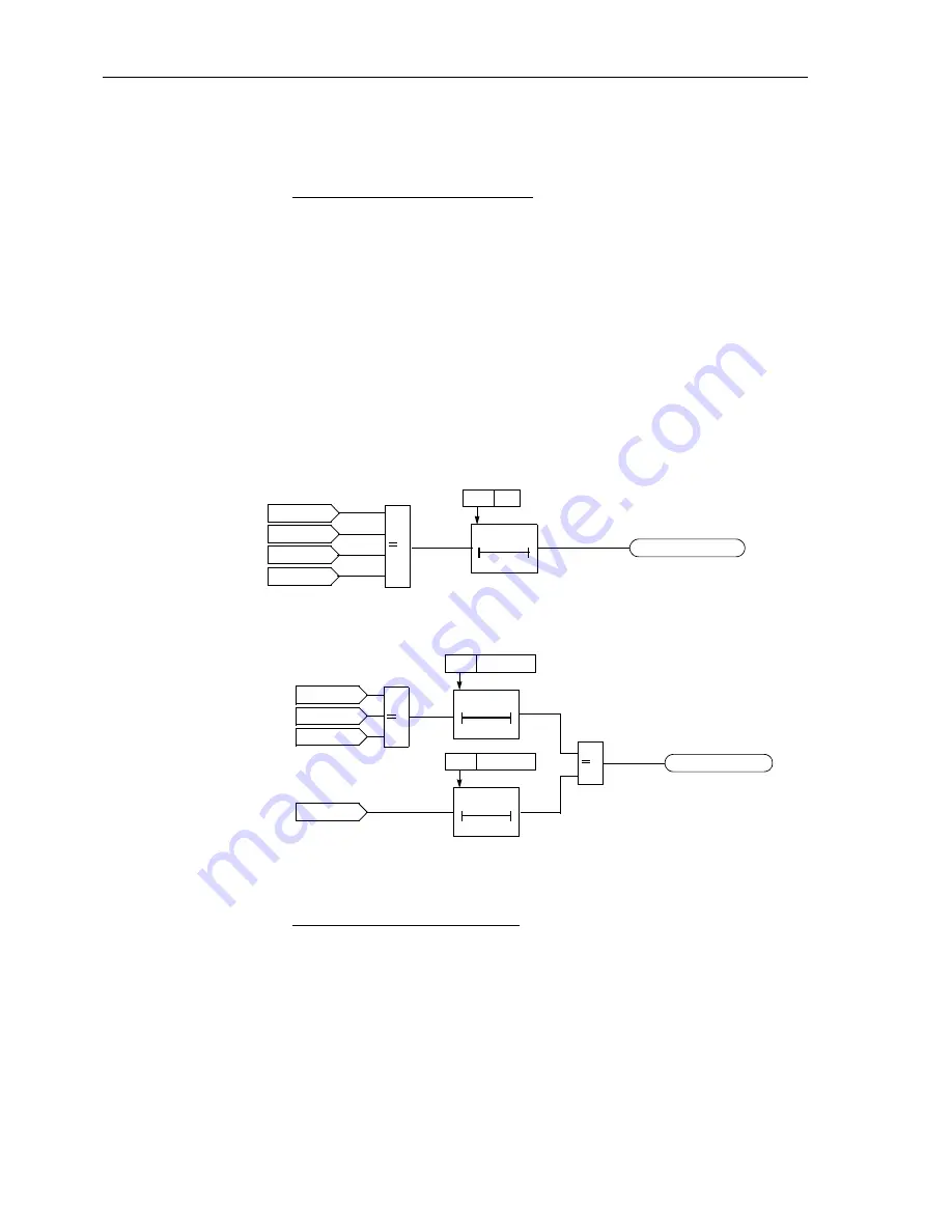
The simplest solution is to start the delay timer
T2
(Figure 6-129). The phase-segre-
gated initiation signals are omitted if the feeder protection always trips three-pole or if
the circuit breaker is not capable of single-pole tripping.
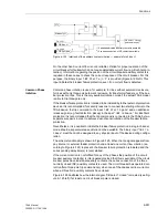
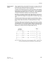
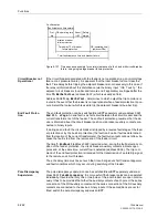
If different delay times are required after a single-pole trip and three-pole trip by the
feeder protection it is possible to use the timer stages
T1-1pole
and
T1-3pole
ac-
cording to Figure 6-130.
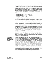
Figure 6-129 Single-stage breaker failure protection with common phase initiation
Figure 6-130 Single-stage breaker failure protection with different delay timers
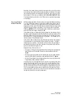
With two-stage breaker failure protection, the trip command of the feeder protection is
usually repeated, after a first time stage, to the feeder circuit breaker, often via a sec-
ond trip coil or set of trip coils, if the breaker has not responded to the original trip com-
mand. A second time stage monitors the response to this repeated trip command and
trips the breakers of the relevant bus-bar section, if the fault has not yet been cleared
after this second time.
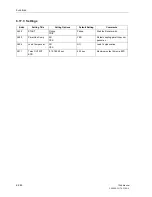
For the first time stage, different time delays can be selected for a single-pole trip and
three-pole trip by the feeder protection. Additionally, you can select (parameter
1p-
RETRIP (T1)
) whether this repeated trip should be single-pole or three-pole.
BF T2-TRIP(bus)
(Trip
bus-bar)
T 0
3906
T2
Start only L1
Start only L2
Start only L3
Start L123
> 1
FNo 1494
BF T1-TRIP L123
Start only L1
Start only L2
Start only L3
Start L123
> 1
T 0
T 0
3904
T1-1Pole
3905
T1-3Pole
> 1
(Trip
bus-bar)
FNo 1476
Summary of Contents for siprotec 7SA6
Page 2: ...Siemens Aktiengesellschaft Book No C53000 G1176 C156 2 ...
Page 18: ...xviii 7SA6 Manual C53000 G1176 C156 2 ...
Page 32: ...Introduction 1 14 7SA6 Manual C53000 G1176 C156 2 ...
Page 82: ...Hardware and Connections 2 50 7SA6 Manual C53000 G1176 C156 2 ...
Page 119: ...SIPROTEC 4 Devices 4 25 7SA6 Manual C53000 G1176 C156 2 Figure 4 20 CFC Logic example ...
Page 190: ...Configuration 5 62 7SA6 Manual C53000 G1176 C156 2 ...
Page 652: ...Installation and Commissioning 8 78 7SA6 Manual C53000 G1176 C156 2 ...
Page 724: ...Technical Data 10 56 7SA6 Manual C53000 G1176 C156 ...
Page 800: ...Appendix A 76 7SA6 Manual C53000 G1176 C156 2 ...
Page 866: ...Appendix B 66 7SA6 Manual C53000 G1176 C156 2 ...

