Functions
6-296
7SA6 Manual
C53000-G1176-C156-2
6.22.3 Overall Fault Detection Logic of the Device
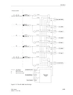
Phase Segregated
Fault Detection
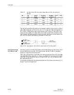
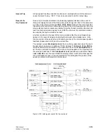
The fault detection logic combines the fault detection (pick-up) signals of all protection
functions. In the case of those protection functions that allow for phase segregated
pick-up, the pick-up is output per phase. If a protection function detects an earth fault,
this is also output as a common device alarm. The following alarms are therefore avail-
able “
Relay PICKUP L1
”, “
Relay PICKUP L2
”, “
Relay PICKUP L3
” and “
Relay
PICKUP E
”.
The annunciations above can be allocated to LEDs or output relays. For the local dis-
play of fault event messages (trip log) and for the transmission of event messages to
a personal computer or a centralized control system, several protection functions pro-
vide the possibility to display the faulted phase information in a single message, e.g.
“
Dis.Pickup L12E
” for the distance protection fault detection in L1–L2–E only one
such messages appears. It represents the complete definition of the fault detection.
General Fault
Detection
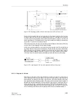
All fault detection signals are combined with a logic OR function and cause a general
fault detection of the device. It is designated with “
Relay PICKUP
”. If no protection
function is picked-up anymore, the “
Relay PICKUP
” will reset (message “Going”).
The general fault detection is a prerequisite for a number of internal and external con-
sequential functions. The following belong to the internal functions which are control-
led by the general fault detection:
•
Initiation of a fault event report (trip log): from the pick-up to the reset of the general
fault detection the fault messages are stored in the trip log.
•
Initialisation of the fault recording: the storage of analogue and binary traces can
additionally be made dependant on the appearance of a trip command.
•
Generation of spontaneous messages. Certain fault messages may appear in the
display of the device as so called spontaneous messages (see “Spontaneous Mes-
sages” below). This display may additionally be made dependant on the appear-
ance of a trip command.
•
Start action time of automatic reclosure (if available and used)
External functions may be controlled via an output contact. The following are exam-
ples:
•
Automatic reclose devices,
•
Channel boost in conjunction with signal transmission by PLC,
•
Initiation of further supplementary devices etc.
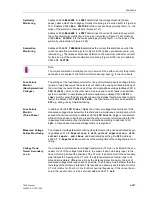
Spontaneous
Messages
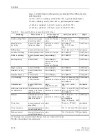
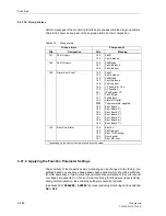
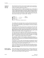
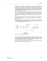
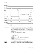
Spontaneous messages are fault messages which appear in the display automatically
following a general fault detection of the device or trip command. In the 7SA6 these
are:
•
“
Relay PICKUP
”: protection function which picked up most recently;
•
”
Relay TRIP
”:
protection function which tripped (only device with graphic
display);
•
“
PU Time
”:
the duration from pickup to reset of the general fault
detection of the device; the time is indicated in ms;
•
“
TRIP Time
”:
the duration from pickup to the of the first trip command of the
device; the time is indicated in ms;
Summary of Contents for siprotec 7SA6
Page 2: ...Siemens Aktiengesellschaft Book No C53000 G1176 C156 2 ...
Page 18: ...xviii 7SA6 Manual C53000 G1176 C156 2 ...
Page 32: ...Introduction 1 14 7SA6 Manual C53000 G1176 C156 2 ...
Page 82: ...Hardware and Connections 2 50 7SA6 Manual C53000 G1176 C156 2 ...
Page 119: ...SIPROTEC 4 Devices 4 25 7SA6 Manual C53000 G1176 C156 2 Figure 4 20 CFC Logic example ...
Page 190: ...Configuration 5 62 7SA6 Manual C53000 G1176 C156 2 ...
Page 652: ...Installation and Commissioning 8 78 7SA6 Manual C53000 G1176 C156 2 ...
Page 724: ...Technical Data 10 56 7SA6 Manual C53000 G1176 C156 ...
Page 800: ...Appendix A 76 7SA6 Manual C53000 G1176 C156 2 ...
Page 866: ...Appendix B 66 7SA6 Manual C53000 G1176 C156 2 ...

