Functions
6-306
7SA6 Manual
C53000-G1176-C156-2
6.23
Supplementary Functions
The auxiliary functions of the 7SA6 relay include:
•
processing of messages,
•
processing of operational measured values,
•
storage of fault record data.
6.23.1 Processing of Messages
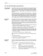
For the detailed fault analysis, the information regarding the reaction of the protection
device and the measured values following a system fault are of interest. For this pur-
pose, the device provides information processing which operates in a threefold man-
ner:
Indicators (LEDs)
and Binary Outputs
(Output Relays)
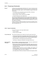
Important events and states are indicated with optical indicators (LED) on the front
plate. The device furthermore has output relays for remote indication. Most of the sig-
nals and indications can be marshalled, i.e. routing can be changed from the preset-
ting with delivery. In Chapter 5 and Appendix A the state of the delivered relay (pre-
setting) and marshalling facilities are extensively discussed.
The output relays and the LEDs may be operated in a latched or unlatched mode
(each may be individually set).
The latched state is saved against loss of auxiliary supply. It is reset:
−
locally by operation of the key LED reset on the front of the device,
−
from remote via a binary input,
−
via one of the serial interfaces,
−
automatically on detection of a new fault.
Condition messages should not be latched. Also, they cannot be reset until the crite-
rion to be reported has reset. This applies to e.g. messages from monitoring functions,
or similar.
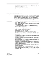
A green LED indicates that the device is in service (“RUN”); it can not be reset. It ex-
tinguishes if the self-monitoring of the microprocessor recognizes a fault or if the aux-
iliary supply fails.
In the event that the auxiliary supply is available while there is an internal device fail-
ure, the red LED (“ERROR”) is illuminated and the device is blocked.
DIGSI
®
4 allows you to control the output relays and LEDs of the device selectively,
and thus to check the correct connections to the plant, e.g. during the commissioning
phase. For instance, you can cause each of the output relays to pick up individually
and thus check the wiring between the 7SA6 and the plant without having to generated
the annunciations allocated to them.
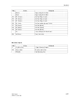
Information via
Integrated Display
(LCD) or a
Personal Computer
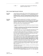
Events and states can be obtained from the LCD on the front plate of the device. A
personal computer can be connected to the front interface or the service interface for
retrieval of the information.
Summary of Contents for siprotec 7SA6
Page 2: ...Siemens Aktiengesellschaft Book No C53000 G1176 C156 2 ...
Page 18: ...xviii 7SA6 Manual C53000 G1176 C156 2 ...
Page 32: ...Introduction 1 14 7SA6 Manual C53000 G1176 C156 2 ...
Page 82: ...Hardware and Connections 2 50 7SA6 Manual C53000 G1176 C156 2 ...
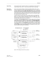
Page 119: ...SIPROTEC 4 Devices 4 25 7SA6 Manual C53000 G1176 C156 2 Figure 4 20 CFC Logic example ...
Page 190: ...Configuration 5 62 7SA6 Manual C53000 G1176 C156 2 ...
Page 652: ...Installation and Commissioning 8 78 7SA6 Manual C53000 G1176 C156 2 ...
Page 724: ...Technical Data 10 56 7SA6 Manual C53000 G1176 C156 ...
Page 800: ...Appendix A 76 7SA6 Manual C53000 G1176 C156 2 ...
Page 866: ...Appendix B 66 7SA6 Manual C53000 G1176 C156 2 ...

