Control During Operation
7-53
7SA6 Manual
C53000-G1176-C156-2
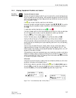
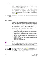
Enter the
BREAKER/SWITCH
menu by pressing the
key.
Select the item
Set Status
with the
key and switch to the next option using the
key.
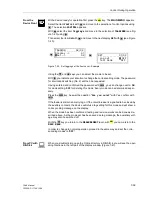
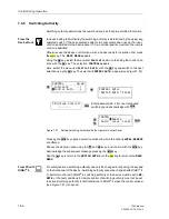
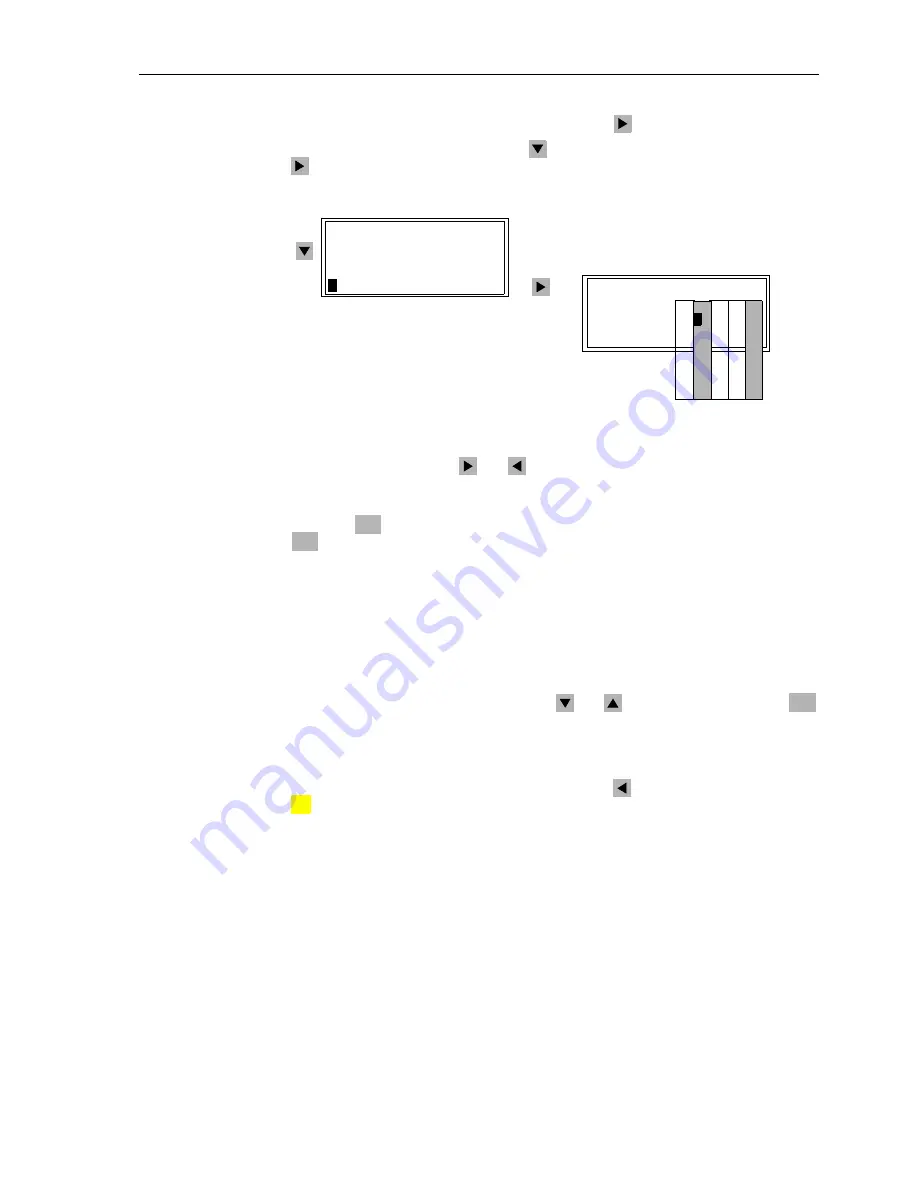
SET STATUS
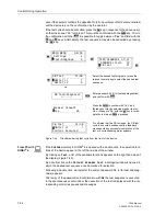
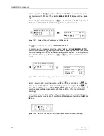
appears, as shown in Figure 7-54.
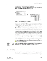
Figure 7-54
Set Status at the Front Panel (example)
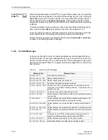
Move the cursor, using the
and
keys, to the second (Input Ignore) or fifth (Con-
trol Block) column of the switching device for which a status change is desired. Entries
in this table can only be made in these two columns.
Press the
key. Enter password N° 2 (for interlocked switching) and confirm with
. A selection window is opened displaying all change options that are available.
The second column is reserved for setting Input Ignore (I); the fifth for setting the out-
put block (O). The first, third, and fourth columns can only be read in this menu.
The example in Figure 7-54 shows the position for the circuit breaker (52) was tagged
(T) after the input ignore (I) was set, which means the message input was de-coupled
from the system. The output block is active (O), so the command output is also de-
coupled from the system. For the disconnect switch and the ground switch, no limita-
tions are set.
Select the desired change option using the
and
keys, and confirm with the
key.
A safety inquiry appears: “
Are you sure?
” If the response is “
YES
”, and provided
the return routing is allowed, then the display gives an appropriate message.
To return to the
BREAKER/SWITCH
level, press the
key as necessary. Press the
key to return to the
MAIN MENU
.
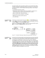
From PC
Using
DIGSI
®
4
For safety reasons, status changes can only be executed locally using the keypad on
the front panel of the device. Status changes are not possible in DIGSI
®
4.
7.4.4
Interlocking
Operating equipment such as circuit breakers, circuit switchers and ground switches
can be subject to interlocking conditions. These conditions can be viewed at the de-
vice under the menu item
INTERLOCK
; however, the conditions cannot be changed.
1. 2. 3. 4. 5.
Col-
BREAKER/SWITCH 04/04
---------------------
Display —> 1
Control –> 2
>
Man. Overwrite –> 3
>
Set status —> 4
SET STATUS 02/03
--------------------
52Breaker T I - - O
Disc.Swit.-
>
- - - -
GndSwit. - - - - -
ENTER
ENTER
ENTER
MENU
:
Summary of Contents for siprotec 7SA6
Page 2: ...Siemens Aktiengesellschaft Book No C53000 G1176 C156 2 ...
Page 18: ...xviii 7SA6 Manual C53000 G1176 C156 2 ...
Page 32: ...Introduction 1 14 7SA6 Manual C53000 G1176 C156 2 ...
Page 82: ...Hardware and Connections 2 50 7SA6 Manual C53000 G1176 C156 2 ...
Page 119: ...SIPROTEC 4 Devices 4 25 7SA6 Manual C53000 G1176 C156 2 Figure 4 20 CFC Logic example ...
Page 190: ...Configuration 5 62 7SA6 Manual C53000 G1176 C156 2 ...
Page 652: ...Installation and Commissioning 8 78 7SA6 Manual C53000 G1176 C156 2 ...
Page 724: ...Technical Data 10 56 7SA6 Manual C53000 G1176 C156 ...
Page 800: ...Appendix A 76 7SA6 Manual C53000 G1176 C156 2 ...
Page 866: ...Appendix B 66 7SA6 Manual C53000 G1176 C156 2 ...

