Appendix
A-27
7SA6 Manual
C53000-G1176-C156-2
A.2.2
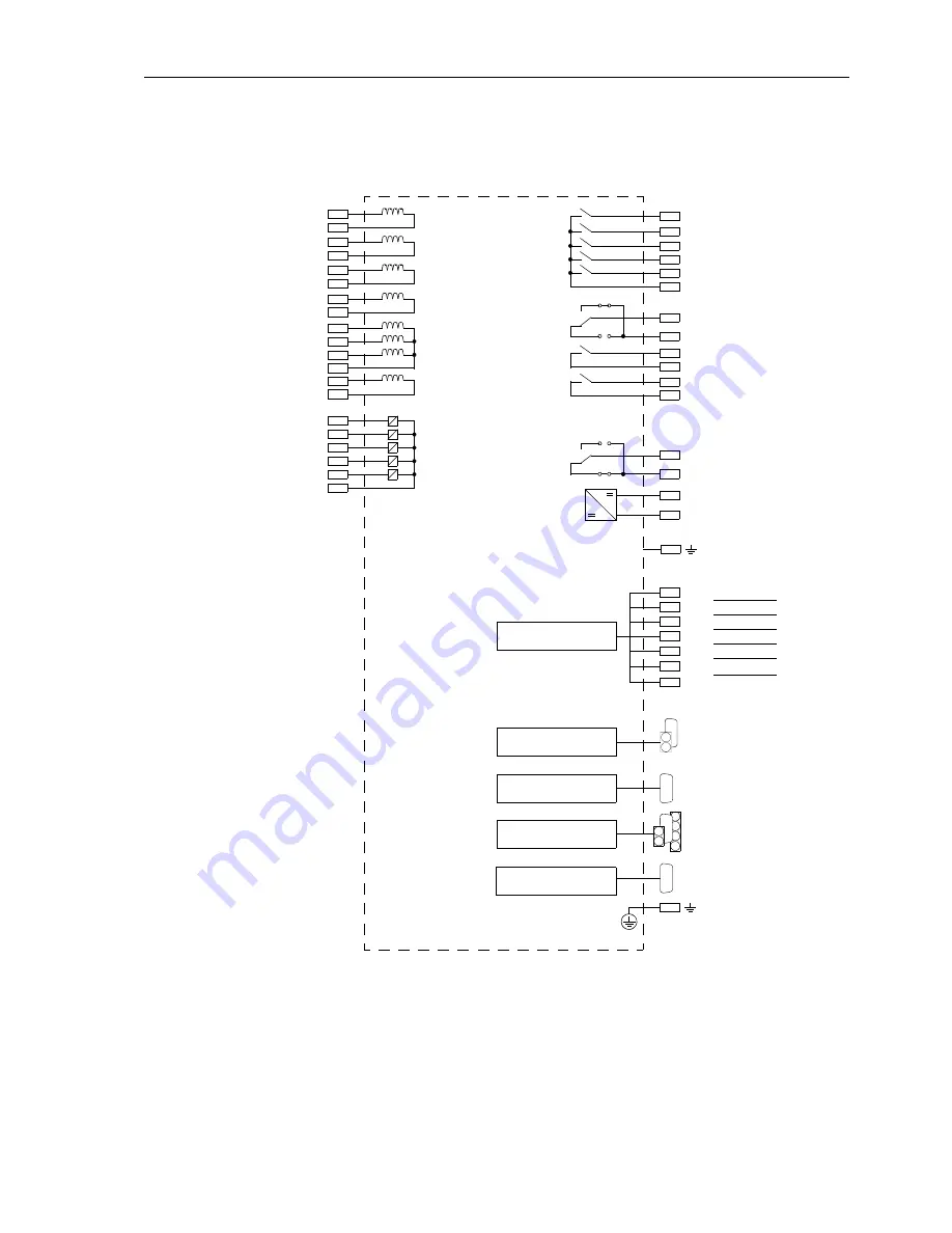
Panel Surface Mounting
7SA610
∗
–
∗
E
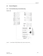
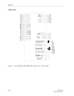
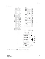
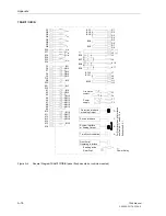
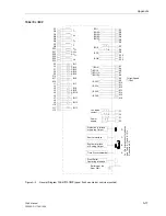
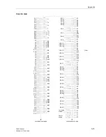
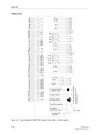
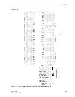
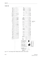
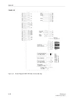
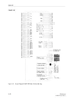
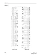
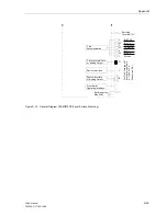
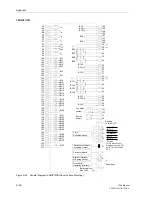
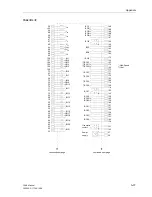
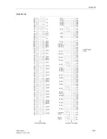
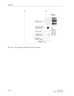
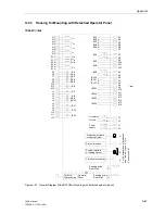
Figure A-13
General Diagram 7SA610
∗
−
∗
E (Panel Surface Mounting)
Power
Earthing at the
supply
Side Wall
54
39
BO7
10
11
( )
~
+
-
Live status
31
32
contact
1 2
3 2
15
30
I
L1
14
29
I
L2
13
28
I
L3
26
25
U
4
45
44
U
L1
60
U
L2
59
U
L3
37
36
BI1
34
33
52
35
BI2
BI4
BI5
BI3
42
57
BO3
41
BO4
56
BO5
58
BO2
43
BO1
55
40
1 2
3 2
BO6
53
38
BO8
Earthing
Terminal (16)
12
27
I
4
2
17
3
19
18
4
1
Time
Synchronisation
IN 12 V
IN SYNC
COM SYNC
COMMON
IN 24 V
Screen
IN 5 V
For
P
in
A
lloc
a
tions
of
In
te
rf
ac
es
see
T
able
8
-11
and
8-12
in
S
ubsec
ti
on
8.
2.
1
System Interface
or Analog Output
B
Sevice Interface
C
D
Front Serial
Operating Interface
Protection Interface
or Analog Output
Summary of Contents for siprotec 7SA6
Page 2: ...Siemens Aktiengesellschaft Book No C53000 G1176 C156 2 ...
Page 18: ...xviii 7SA6 Manual C53000 G1176 C156 2 ...
Page 32: ...Introduction 1 14 7SA6 Manual C53000 G1176 C156 2 ...
Page 82: ...Hardware and Connections 2 50 7SA6 Manual C53000 G1176 C156 2 ...
Page 119: ...SIPROTEC 4 Devices 4 25 7SA6 Manual C53000 G1176 C156 2 Figure 4 20 CFC Logic example ...
Page 190: ...Configuration 5 62 7SA6 Manual C53000 G1176 C156 2 ...
Page 652: ...Installation and Commissioning 8 78 7SA6 Manual C53000 G1176 C156 2 ...
Page 724: ...Technical Data 10 56 7SA6 Manual C53000 G1176 C156 ...
Page 800: ...Appendix A 76 7SA6 Manual C53000 G1176 C156 2 ...
Page 866: ...Appendix B 66 7SA6 Manual C53000 G1176 C156 2 ...

