Appendix
A-43
7SA6 Manual
C53000-G1176-C156-2
7SA641
∗
–
∗
M/P
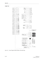
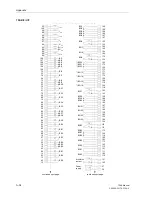
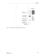
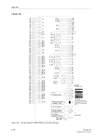
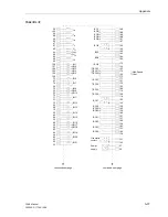
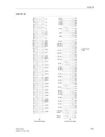
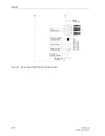
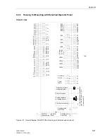
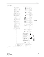
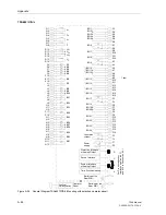
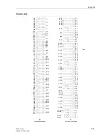
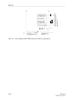
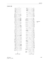
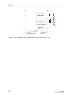
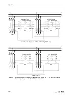
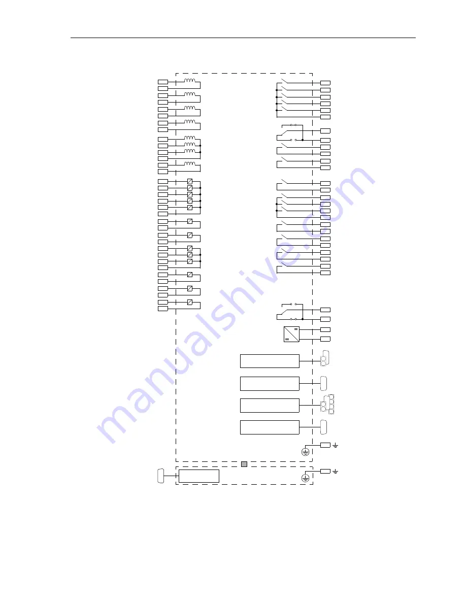
Figure A-25
General Diagram 7SA641
∗
−
∗
M/P (Mounting with detached operator panel)
Power
Earthing at the
supply
Rear Wall
K9
K10
BO13
F1
F2
( )
~
+
-
Live status
F3
F4
contact
1 2
3 2
F
o
r
P
in
Allocat
ions
of
In
te
rf
ac
es
s
e
e
T
able
8
-1
1
and
8-12
in
S
ubsect
ion
8.
2.
1
Q1
Q2
I
L1
Q3
Q4
I
L2
Q5
Q6
I
L3
R13
R14
U
4
R15
R17
U
L1
R18
U
L2
R16
U
L3
F5
F6
BI1
F8
F9
F10
F7
BI2
BI4
BI5
BI3
K11
K12
BO14
K6
K7
BO10
K8
BO11
K5
BO12
K17
K18
BI6
J1
J2
BI7
J4
J6
J5
J3
BI9
BI10
BI8
J7
J8
BI11
J9
J10
BI12
J11
J12
BI13
R3
R4
BO3
R6
BO4
R5
BO5
R2
BO2
R1
BO1
R7
R8
1 2
3 2
BO6
R9
R10
BO7
R11
R12
BO8
K13
K14
BO15
K15
K16
BO16
K3
K4
*) BO9
**)
*)
*)
*)
**)
**)
*)
Earthing at the
Rear Wall
Q7
Q8
I
4
System Interface
or Analog Output
B
A
Time Synchronisation
Sevice Interface
C
D
Front Serial
Operating Interface
Operator
Panel
*) High-Speed
**) fast
Protection Interface
or Analog Output
Summary of Contents for siprotec 7SA6
Page 2: ...Siemens Aktiengesellschaft Book No C53000 G1176 C156 2 ...
Page 18: ...xviii 7SA6 Manual C53000 G1176 C156 2 ...
Page 32: ...Introduction 1 14 7SA6 Manual C53000 G1176 C156 2 ...
Page 82: ...Hardware and Connections 2 50 7SA6 Manual C53000 G1176 C156 2 ...
Page 119: ...SIPROTEC 4 Devices 4 25 7SA6 Manual C53000 G1176 C156 2 Figure 4 20 CFC Logic example ...
Page 190: ...Configuration 5 62 7SA6 Manual C53000 G1176 C156 2 ...
Page 652: ...Installation and Commissioning 8 78 7SA6 Manual C53000 G1176 C156 2 ...
Page 724: ...Technical Data 10 56 7SA6 Manual C53000 G1176 C156 ...
Page 800: ...Appendix A 76 7SA6 Manual C53000 G1176 C156 2 ...
Page 866: ...Appendix B 66 7SA6 Manual C53000 G1176 C156 2 ...


