


Mounting and Commissioning
3.3 Commissioning
SIPROTEC, 7SC805, Manual
C53000-G1140-C380-1, Release date 05.2014
102
3.3.6
Current, Voltage Testing
Preliminary Remark
Note
The voltage and phase rotation test is only relevant for devices with voltage transformers.
10 % of Load Current
The connections of the current and voltage transformers are tested using primary quantities. Secondary load
current of at least 10 % of the nominal current of the device is necessary. The line is energized and will remain
in this state during the measurements.
With proper connections of the measuring circuits, none of the measured-values supervision elements in the
device should pick up. If an element detects a problem, the causes which provoked it may be viewed in the
Event Log. If current or voltage summation errors occur, then check the matching factors.
Messages from the symmetry monitoring could occur because there actually are asymmetrical conditions in
the network. If these asymmetrical conditions are normal service conditions, the corresponding monitoring
functions should be made less sensitive.
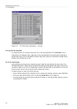
Current and Voltage Values
Currents and voltages can be read out via a PC using the Web Monitor or the operator interface, and compared
with the actual measured quantities, as primary and secondary quantities.
If the measured values are not plausible, the connection must be checked and corrected after the line has been
isolated and the current transformer circuits have been short-circuited. The measurements must then be re-
peated.
Note
If the voltage measurement is carried out via feed through capacitances, the display of the values of the phase-
to-ground voltages and phase angle between the phase-to-ground voltages and the phase currents can be
used to optimize the configured capacitance values afterwards and to achieve an improvement of the measur-
ing accuracy. An explanation of the procedure for optimizing the input capacitances is to be found in Section
2.1.2.2, “Capacitive Voltage Measurement”.
Voltage Transformer Miniature Circuit Breaker (VT mcb)
The VT mcb of the feeder (if used) must be opened. The measured voltages in the operational measured
values appear with a value close to zero (small measured voltages are of no consequence).
Check in the spontaneous annunciations that the VT mcb trip was entered (annunciation
“>FAIL:FEEDER VT”
“ON” in the spontaneous annunciations). Beforehand it has to be assured that the position of the VT mcb is
connected to the device via a binary input.
Close the VT mcb again: The above messages appear under the spontaneous messages as “
OFF
”, i.e.
“>FAIL:FEEDER VT” “OFF
”.
If one of the events does not appear, the connection and allocation of these signals must be checked.
If the
“ON”
-state and
“OFF”
–state are swapped, the contact type (H–active or L–active) must be checked and
remedied.


