


Appendix
A.1 Ordering Information and Accessories
SIPROTEC, 7SC805, Manual
C53000-G1140-C380-1, Release date 05.2014
128
A.1
Ordering Information and Accessories
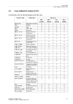
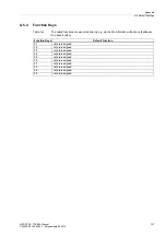
A.1.1
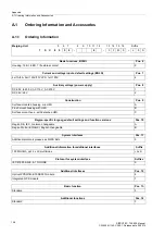
Ordering Information
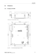
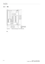
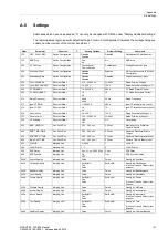
Merging Unit
5
6
7
8
9
10 11 12
13 14 15 16
Suffix
7
S
C
8
0
5
4
–
9
–
3
F
M
0
+
L
9
S
Basic functions, BO/BI
Pos. 6
Housing, 12 BI, 8 BO, 1 life status contact
5
Current and voltage inputs, default settings (BOLD)
Pos. 7
4xI 1A/5A, 3xU 120V/10V LPS, 1xU 120V
4
Auxiliary voltage (power supply)
Pos. 8
DC 60 V to 250 V, AC 115 V, AC 230 V
1
DC 24 V/48 V
2
Construction
Pos. 9
Surface-mounted housing, w/o HMI
A
Flush mount housing with HMI
B
Surface mount.hous., with detached HMI
C
Region-specific language default settings and function versions
Pos. 10
Region DE, IEC, German changeable
A
Region World, IEC/ANSI, English changeable
B
System interfaces
Pos. 11
Additional protocols please see MLFB Ext.L
9
Additional information for additional interfaces
Suffix
100 Mbit Eth, opt. 2 x LC multimode
+ L x S
Protocol for system interface
Suffix x
IEC 61850 9-2LE, 8-1 GOOSE
9
Additional interfaces
Pos. 12
Optical PPS/IRIG-B 005/B007 module
6
Integrated GPS module
7
Basic function
Pos. 13,
Standard
3
Additional functions
Pos. 14
Standard
F


