


Functions
2.1 General
SIPROTEC, 7SC805, Manual
C53000-G1140-C380-1, Release date 05.2014
23
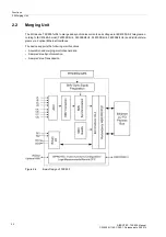
2.1.2
Power System Data 1
2.1.2.1
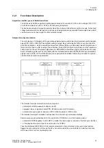
Description
The device requires certain data regarding the network and substation so that it can adapt its functions to this
data depending on the application. This may be, for instance, nominal data of the substation and measuring
transformers, polarity and connection of the measured quantities, breaker properties (where applicable), etc.
There are also certain parameters that are common to all functions, i.e. not associated with a specific control
or monitoring function. The following section discusses this data.
2.1.2.2
Setting Notes
The following parameters are only for CTs and VTs. For the other special setting notes of Merging Unit, please
refer to chapter
. There are two possibilities for configuring CTs and VTs: 1-phase or 3-phase system con-
figuration.These two configurations share some common parameters and also have their own parameters.
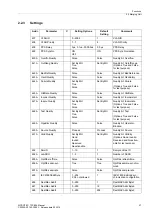
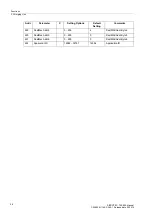
General
In DIGSI, double-click
Settings
to open the corresponding dialog box. In doing so, a dialog box with tabs opens
under
P.System Data 1
, in which individual parameters can be configured. The following descriptions are there-
fore structured according to these tabs.
Rated Frequency (Power System)
The rated system frequency is set at address 0
214
Rated Frequency
. The factory setting of the model number
must only be changed if the device is to be used for a different purpose than intended when ordering. Parameter
214
is preset to 50 Hz.
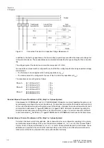
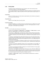
Capacitive Voltage Measurement
If you select the setting
Cap. Volt.Meas.
at address
369
VT Con Type
, the voltage is measured via so-called
bushing capacitances. The inductive primary voltage transformers normally used are not used in this case. Ca-
pacitive voltage measurement always measures the phase-to-ground voltages from the device. The following
figure shows this type of connection.


