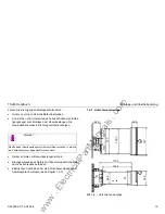
background image

7SJ46 Handbuch

Technische Daten

C53000-K1174-C002-4

29

Mechanische Prüfungen

Schwing- und Schockbeanspruchung bei stationärem Einsatz

Schwing- und Schockbeanspruchung beim Transport
(nur Einbauversion)

Normen

IEC 60255–21 und IEC 60068–2

Schwingung
IEC 60255–21–1, Klasse 2
IEC 60068–2–6

Sinusförmig
10 Hz bis 60 Hz: ±0,075 mm Amplitude;
60 Hz bis 150 Hz: 1 g Beschleunigung
Frequenzdurchlauf 1 Oktave/min
20 Zyklen in 3 Achsen senkrecht zueinander

Schock IEC 60255–21–2, Klasse 1 Halbsinusförmig

5 g Beschleunigung, Dauer 11 ms,
je 3 Schocks in beiden Richtungen der
3 Achsen

Schwingung bei Erdbeben
IEC 60255–21–3, Klasse 1
IEC 60068–3–3

Sinusförmig
1 Hz bis 8 Hz: ±4,0 mm Amplitude (horizon-
tale Achsen)
1 Hz bis 8 Hz: ±2,0 mm Amplitude (vertikale
Achse)
8 Hz bis 35 Hz: 1 g Beschleunigung (hori-
zontale Achsen)
8 Hz bis 35 Hz: 0,5 g Beschleunigung (verti-
kale Achse)
Frequenzdurchlauf 1 Oktave/min
1 Zyklus in 3 Achsen senkrecht zueinander

Normen

IEC 60255–21 und IEC 60068–2

Schwingung
IEC 60255–21–1, Klasse 2
IEC 60068–2–6

Sinusförmig
5 Hz bis 8 Hz: ±7,5 mm Amplitude;
8 Hz bis 150 Hz: 2 g Beschleunigung
Frequenzdurchlauf 1 Oktave/min
20 Zyklen in 3 Achsen senkrecht zueinander

Schock
IEC 60255–21–2, Klasse 1
IEC 60068–2–27

Halbsinusförmig
15 g Beschleunigung, Dauer 11 ms,
je 3 Schocks in beiden Richtungen der
3 Achsen

Dauerschock
IEC 60255–21–2, Klasse 1
IEC 60068–2–29

Halbsinusförmig
10 g Beschleunigung, Dauer 16 ms, je 1000
Schocks in beiden Richtungen der 3 Achsen

www 

. ElectricalPartManuals 

. com

Summary of Contents for SIPROTEC 7SJ46

Page 1: ... 2 3 4 5 6 ON ON ON 8 4 2 1 0 5 0 25 3 2 1 6 0 8 0 4 0 2 0 1 TI MIN 0 MAX 6 3 D MIN 0 5 MAX 15 s 3 2 1 6 0 8 0 4 0 2 0 1 3 2 1 6 0 8 0 4 0 2 0 1 I MIN 0 5 MAX 6 2 Ip MIN 0 5 MAX 4 I I N 0 8 0 4 0 2 0 1 0 05 0 025 TI MIN 0 MAX 1 575 s 0 8 0 4 0 2 0 1 0 05 0 025 TI MIN 0 MAX 1 575 16 8 4 2 1 0 5 I MIN 2 MAX 20 I I N 16 8 4 2 1 0 5 I MIN 2 MAX 20 NOT STORED STORED LED S TRIP L1 L3 L2 N ENTER RUN ERRO...

Page 2: ...en 11 1 7 1 Grundeinstellungsblock 11 1 7 2 Parametereinstellungen 13 1 8 Gerätekonfiguration über Steckbrücke 16 1 9 Montage und Inbetriebsetzung 18 1 9 1 Schalttafeleinbau 18 1 9 2 Hutschienenmontage 19 1 9 3 Anschluss 21 1 9 4 Inbetriebsetzung 22 1 10 Wartung 25 1 11 Technische Daten 26 2 Operating Instructions 41 2 1 Conformity 41 2 2 General Information 41 2 2 1 Qualified personnel 42 2 2 2 U...

Page 3: ...ettings 48 2 7 1 Basic Settings Block 48 2 7 2 Parameter settings 50 2 8 Configuration by jumpers 53 2 9 Installation and commissioning 55 2 9 1 Panel flush mounting 55 2 9 2 Standard rail mounting 56 2 9 3 Connection 58 2 9 4 Commissioning 59 2 10 Maintenance 62 2 11 Technical Data 63 w w w E l e c t r i c a l P a r t M a n u a l s c o m ...

Page 4: ...3 Das Produkt ist im Rahmen der Technischen Daten UL zugelassen 1 2 Allgemeine Hinweise Diese Betriebsanleitung enthält die erforderlichen Informationen für den bestimmungsgemäßen Gebrauch der darin beschriebe nen Produkte Sie wendet sich an technisch qualifiziertes Perso nal welches speziell ausgebildet ist oder einschlägiges Wissen auf dem Gebiet der Mess Steuerungs und Regelungstechnik im folge...

Page 5: ...ie Ausführungen in dieser Unterlage weder erweitert noch beschränkt 1 2 1 Qualifiziertes Personal sind Personen die mit Aufstellung Montage Inbetriebsetzung und Betrieb des Produktes vertraut sind und über entsprechende Qualifikationen verfügen wie z B Ausbildung oder Unterweisung bzw Berechtigung Geräte Systeme gemäß den Standards der Sicherheitstechnik ein und auszuschalten zu erden und zu kennz...

Page 6: ...den Inhalt der Druckschrift auf Übereinstimmung mit der beschriebenen Hard und Software geprüft Dennoch können Abweichungen nicht ausgeschlossen werden so dass wir für die vollständige Übereinstimmung keine Gewähr übernehmen Die Angaben in diesem Handbuch werden regelmäßig überprüft und notwendige Korrekturen sind in den nachfolgenden Auflagen enthalten Für Verbesserungsvorschläge sind wir dankbar...

Page 7: ...ert werden Für die Lagerung des Gerätes oder zugehöriger Ersatzbaugruppen gilt der Temperaturbereich von 25 C bis 55 C siehe auch Kapitel 1 11 Es wird empfohlen bei der Lagerung einen eingeschränkten Temperaturbereich zwischen 10 C und 35 C einzuhalten um einer vorzeitigen Alterung der eingesetzten Elektrolytkonden satoren vorzubeugen Bei der nicht betauungsfesten Ausführung des Gerätes darf die r...

Page 8: ...bleibt für mindestens 500 ms anstehen Bei einer Auslösung bleibt das Aus Kommando anstehen bis die Anregung zurückfällt Überwachungsfunktionen Überwachung der Hardware und Software dadurch erhöhte Zuverlässigkeit Die Überwachung steuert den Live Kontakt und die LED RUN ERROR 1 6 Aufbau Das Schutzgerät 7SJ46 enthält in kompakter Bauform alle Kom ponenten Messwerterfassung und Auswertung Meldungs un...

Page 9: ... der Anrege LED und Test der LEDs 4 DIP Schalter Zur Parametrierung des Gerätes stehen fünf 6 polige DIP Schalter zur Verfügung Die möglichen Einstellungen werden im Kapitel Parametereinstellungen beschrieben SIPROTEC7SJ4 1 2 3 4 5 6 ON 60 Hz 50 Hz FREQ IE I MODE M INV V INV E INV ANSI 51 DT O C 50 51 1 2 3 4 5 6 1 2 3 4 5 6 1 2 3 4 5 6 ON 1 2 3 4 5 6 ON ON ON 8 4 2 1 0 5 0 25 3 2 1 6 0 8 0 4 0 2 ...

Page 10: ...kseite Bild 1 3 befinden sich die Anschluss leisten mit den Schraubklemmen Rückansicht Bild 1 3 Geräterückseite Anschlüsse 7SJ46 Das Leistungsschild mit den für das Gerät wichtigen Daten befin det sich seitlich am Gehäuse ANSI IEC Phase Erdstrom Phase Erdstrom w w w E l e c t r i c a l P a r t M a n u a l s c o m ...

Page 11: ...alle DIP Schalter auf der Front in Schalterstel lung off bei Blick auf die Front Schalter nach rechts gescho ben Durch Ändern der Schalterstellung der einzelnen DIP Schalter wird das Gerät parametriert Führen Sie dazu einen dünnen Gegenstand Stift in die Kerbe ein und bewegen den Schalter in die gewünschte Position Bild 1 4 Schalterbelegung DIP Schalter 1 7 1 Grundeinstellungsblock Mit dem Grundei...

Page 12: ...sind alle Schutzstufen deaktiviert Wählen Sie nur eine Überstromzeitschutz Kennlinie aus Um die korrigierte Einstellung zu übernehmen betätigen Sie die Taste ENTER Die LED RUN ERROR hört nun auf zu blin ken siehe Kapitel 1 9 4 Folgende Typen von abhängigen Überstromzeitschutz Kennlinien können ausgewählt werden Die Überstromzeitschutzkennlinien finden Sie im Abschnitt Tech nische Daten siehe Bild ...

Page 13: ...estellt für Netzfre quenz 50 Hz Hochstromstufe aktiv Betriebsart abhängiger Über stromzeitschutz Kennlinien art Very inverse NOT STORED 60 Hz IE LEDs STORED FREQ MODE N INV V INV E INV IEC 51 DT O C 50 51 50 Hz I NOT STORED 60 Hz IE LEDs STORED FREQ MODE N INV V INV E INV IEC 51 DT O C 50 51 50 Hz I Tabelle 1 2 Parameterzuordnung DIP Schalter 2 bis 5 siehe Bild 1 1 auf Seite 9 SW 1 MODE I Hochstro...

Page 14: ...chten dass der Einstellwert unterhalb des für den geplanten Schutzbe reich zu erwartenden kleinsten Kurzschlussstromes liegt Die Einstellzeiten sind dem für das Netz aufgestellten Staffelplan zu entnehmen In der Betriebsart als abhängiger Überstromzeitschutz ist zu be achten dass die eingestellen Kennlinien zweier benachbarter Relais mindestens einen Abstand von einer Staffelzeit ca 0 3 s haben Di...

Page 15: ...e zugehörige Schutzstufe unwirksam geschaltet werden kann Dazu sind alle Schalter in Schalterstellung on zu bringen Stromwandler INP INS 100 A 1 A Nennstrom des Gerätes IN 1 A maximaler Betriebstrom 120 A Sicherheitsfaktor angenommen 1 25 Ip 120A 100A INS IN 1 25 1 5 IN Einstellwert Schalterwerte å Tabelle 1 3 Beispiele Parametereinstellung mit DIP Schaltern Para meter Schalterstel lung Bedeutung ...

Page 16: ...uration über Steckbrücke Mit Hilfe von Steckbrücken auf der Flachbaugruppe können einige Grundeinstellungen am Gerät verändert werden siehe Bild 1 6 Durch Umschalten der Steckbrücke X25 kann das Relais Klem me X1_6 und X1_7 entweder als Auslöserelais Stellung 2 3 oder als Melderelais für Generalanregung verwendet werden Die Stellung 1 2 der Steckbrücke X25 ist die werkseitige Vorein stellung WARNU...

Page 17: ...cker X25 X61 X62 X63 umsetzen Bild 1 6 ver anschaulicht die Lage der Steckbrücken auf der Baugruppe Nach der Umkonfigurierung wird das Gerät in umgekehrter Reihenfolge zusammengebaut Bild 1 6 Lage der Brücken auf der Baugruppe Tabelle 1 5 Brückenumschaltung Wandlernennstrom X61 X62 X63 IN 1 2 1 A 2 3 5 A Vorsicht Änderung von Leiterplattenelementen die die Nenndaten des Gerä tes betreffen haben zu...

Page 18: ...rper verletzungen oder Sachschäden auftreten Insbesondere müssen alle Warnhinweise unbedingt beachtet werden Das Schutzgerät 7SJ46 ist als Einbaugerät in einen Schaltschrank einzubauen oder für Schalttafelaufbau auf einer Hutschiene zu mon tieren Nach dem Einbau muss der gesamte Klemmenbereich ausrei chend gegen unzulässiges Berühren spannungsführender Teile ge schützt sein 167 3 150 2 38 5 17 1 6...

Page 19: ...eigen Gerät von hinten mit Gewindestangen sichern Erdungsschraube des Gerätes mit Schutzerde der Schalttafel oder des Schrankes verbinden Elektrischen Anschluss über die Schraubanschlüsse nach Anschlussplan herstellen siehe Kapitel 1 9 3 1 9 2 Hutschienenmontage Bild 1 8 Hutschienenmontage Hinweis Das Ende der Gewindestange ist mit einer Hülse versehen in welche ein Schraubendreher eingesteckt wer...

Page 20: ... Gerät mit Hutschienenadapter auf Hutschiene aufschnappen und mit Justierschrauben ausrichten WARNUNG Bevor das Schutzgerät auf einer Hutschiene montiert wird müssen die elektrischen Anschlüsse hergestellt werden Nach der Montage des Gerätes auf der Hutschiene sind die Schraubanschlussblöcke nicht mehr zugänglich Vorsicht Der Hutschienenadapter ist nur für Vor Ort Montage zugelassen Hinweis Es wir...

Page 21: ...hren und so zu sichern dass sie beim Festschrauben nicht wieder herausgeschoben werden Nach dem Anschrauben Anzugsdrehmoment max 1 Nm sind die An schlüsse auf festen Sitz hin zu überprüfen Das Schutzgerät 7SJ46 ist entsprechend dem Anschlussschalt plan anzuschließen Bild 1 9 WARNUNG Der einwandfreie und sichere Betrieb des Gerätes setzt sachgemä ßen Transport fachgerechte Lagerung Aufstellung und ...

Page 22: ...iesem Gerät arbeiten Dieses muss gründlich mit den einschlägigen Sicherheitsvorschriften und Vorsichtsmaßnahmen sowie den Warnhinweisen dieses Handbuches vertraut sein Vor allem ist zu beachten Vor Anschluss irgendwelcher Verbindungen ist das Gerät am Schutzleiteranschluss zu erden Gefährliche Spannungen können in allen mit der Spannungsversorgung und mit den Mess bzw Prüfgrößen verbundenen Schalt...

Page 23: ...rüfeinrich tung ist darauf zu achten dass keine anderen Messgrößen auf geschaltet sind Die Auslöseprüfung sollte mit angeschlossenem Leistungsschalter und mit den für den Betrieb vorgegebenen Ein stellwerten durchgeführt werden Überprüfen Sie ob die Anrege LEDs gespeicherte Anregung an zeigen Gegebenenfalls löschen Sie diese durch Betätigen der Taste LED RESET Speisen Sie mit der Prüfeinrichtung e...

Page 24: ...t anzuziehen Alle Klemmenschrauben auch nicht benutzte müssen fest angezogen werden Überprüfen Sie nochmals die Einstellwerte des Gerätes Insbe sondere kontrollieren Sie die richtige Einstellung des Grundein stellungsblocks Eine erfolgte Änderung der Einstellungen des Gerätes wird nicht sofort übernommen sondern nur durch ein Blinken der LED RUN angezeigt Durch Betätigen der Taste ENTER oder durch...

Page 25: ...rstellerwerk einzusenden Hierzu ist mög lichst die Original Transportverpackung zu verwenden Bei Verwen dung anderer Verpackung muss das Einhalten der Schwing und Schockbeanspruchungen entsprechend IEC 60 255 21 1 Klasse 2 und IEC 60 255 21 2 Klasse 1 sichergestellt werden Vor der Rücksendung sollten alle Projektierungs und Einstellparame ter abgelesen und protokolliert werden Falls Einstellbrücke...

Page 26: ... Phase Erde IN 1 A oder 5 A Leistungsaufnahme bei IN 1 A ca 0 01 VA bei IN bei IN 5 A ca 0 2 VA bei IN Belastbarkeit Strompfad thermisch effektiv 100 IN für 1 s 30 IN für 10 s 4 IN dauernd dynamisch Scheitelwert 250 IN für eine Halbschwingung Eingangsspannungsbereich 24 V DC bis 250 V DC 20 60 V AC bis 230 V AC 20 15 Leistungsaufnahme ca 1 5 W DC ca 3 VA AC bei UH 110 V ca 5 5 VA AC bei UH 230 V A...

Page 27: ...men IEC 60255 6 IEC 60255 22 EN 50263 Produktnormen EN 50082 2 Fachgrundnorm EN 61000 6 2 IEC 61000 4 Basisnormen Hochfrequenzprüfung IEC 60255 22 1 Klasse III 2 5 kV Scheitel 1 MHz τ 15 µs Ri 200 Ω 400 Stöße je s Prüfdauer 2 s Entladung statischer Elektrizität IEC 60255 22 2 Klasse III EN 61000 4 2 Klasse III 4 kV 6 kV Kontaktentladung 8 kV Luftentla dung beide Polaritäten 150 pF Ri 330 Ω Bestrah...

Page 28: ...ert Polarität alternierend 100 kHz 1 MHz 10 MHz und 50 MHz Ri 200 Ω Dauer 2 s Oscillatory Surge Withstand Capa bility ANSI IEEE C37 90 1 nicht über offene Kontakte 2 5 bis 3 kV Scheitelwert 1 bis 1 5 MHz gedämpfte Welle 50 Stöße je s Dauer 2 s Ri 150 Ω bis 200 Ω Fast Transient Surge Withstand Capability ANSI IEEE C37 90 1 nicht über offene Kontakte 4 kV bis 5 kV 10 150 ns 50 und 120 Pulse je s bei...

Page 29: ...8 Hz 4 0 mm Amplitude horizon tale Achsen 1 Hz bis 8 Hz 2 0 mm Amplitude vertikale Achse 8 Hz bis 35 Hz 1 g Beschleunigung hori zontale Achsen 8 Hz bis 35 Hz 0 5 g Beschleunigung verti kale Achse Frequenzdurchlauf 1 Oktave min 1 Zyklus in 3 Achsen senkrecht zueinander Normen IEC 60255 21 und IEC 60068 2 Schwingung IEC 60255 21 1 Klasse 2 IEC 60068 2 6 Sinusförmig 5 Hz bis 8 Hz 7 5 mm Amplitude 8 H...

Page 30: ...hung Standard im Jahresmittel 75 relative Feuchte an 30 Tagen im Jahr bis zu 95 relative Feuchte Betauung ist unzulässig Zulässige Feuchtebeanspruchung Betauungsfest Zulässige Betauung nach IEC 60654 1 Klasse III Gehäuse Schalttafeleinbaugehäuse DIN43700 IEC61554 Aufrüstbar für Hutschienenmontage nur für Vor Ort Montage empfohlen Abmessungen BxHxT 78 5x147x205 8 inkl Vollsichttür und Klem men Gewi...

Page 31: ...der unwirksam Stufung 0 1 IN Stromanregung IE Erde berech net 0 5 IN bis 6 2 IN oder unwirksam Stufung 0 1 IN Verzögerungszeiten T I 0 bis 1575 ms Stufung 25 ms Verzögerungszeiten T I 0 bis 6300 ms Stufung 100 ms Stromanregung Ip Phasen 0 5 IN bis 4 IN oder unwirksam Stufung 0 1 IN Stromanregung IEp Erde berech net 0 5 IN bis 4 IN oder unwirksam Stufung 0 1 IN Verzögerungszeiten T Ip IEC 0 05 bis ...

Page 32: ...l Invers Typ A 0 05 0 1 0 2 0 3 0 5 0 9 0 05 0 1 0 2 0 3 0 5 1 2 3 5 10 20 100 500 0 05 0 10 0 20 0 40 0 80 1 60 3 20 T p s I Ip t s t 9 7 1 I I P 2 è ø ç ç æ ö TP s Normal Invers Typ A 2 3 5 10 20 0 05 0 10 0 20 0 40 0 80 1 60 3 20 T p s I Ip 1 1 100 0 05 0 1 0 2 0 3 0 5 1 2 3 5 10 20 t s t 0 14 I IP 0 02 1 è ø ç ç æ ö TP s w w w E l e c t r i c a l P a r t M a n u a l s c o m ...

Page 33: ...ery Inverse Typ B 0 05 0 1 0 2 0 3 0 5 0 9 0 05 0 1 0 2 0 3 0 5 1 2 3 5 10 20 100 500 0 05 0 10 0 20 0 40 0 80 1 60 3 20 T p s I Ip t s t 43 2 1 I I P 2 è ø ç ç æ ö TP s Very Inverse Typ B 1 1 2 3 5 10 20 0 05 0 10 0 20 0 40 0 80 1 60 3 20 T p s I Ip 0 05 0 1 0 2 0 3 0 5 1 2 3 5 10 20 100 t s t 13 5 I I P 1 è ø æ ö T P s w w w E l e c t r i c a l P a r t M a n u a l s c o m ...

Page 34: ...trem Invers Typ C 0 05 0 1 0 2 0 3 0 5 0 9 0 05 0 1 0 2 0 3 0 5 1 2 3 5 10 20 100 500 0 05 0 10 0 20 0 40 0 80 1 60 3 20 T p s I Ip t s t 58 2 1 I I P 2 è ø ç ç æ ö TP s Extrem Invers Typ C 2 3 5 10 20 0 05 0 10 0 20 0 40 0 80 1 60 3 20 Tp s I Ip 1 1 0 05 0 1 0 2 0 3 0 5 1 2 3 5 10 20 100 t s t 80 I I P 2 1 è ø ç ç æ ö TP s w w w E l e c t r i c a l P a r t M a n u a l s c o m ...

Page 35: ...e M INV 0 05 0 1 0 2 0 3 0 5 0 9 0 05 0 1 0 2 0 3 0 5 1 2 3 5 10 20 100 200 500 0 50 1 00 2 00 5 00 10 00 15 00 D s I Ip t s t 0 97 1 I I P 2 è ø ç ç æ ö D s 2 3 5 10 20 0 50 1 00 2 00 5 00 10 00 15 00 D s I Ip 0 05 0 1 0 2 0 3 0 5 1 2 3 5 10 20 100 200 500 t s 1 1 t 0 0103 I I P 0 02 1 0 0228 è ø ç ç æ ö D s w w w E l e c t r i c a l P a r t M a n u a l s c o m ...

Page 36: ...INV 0 05 0 1 0 2 0 3 0 5 0 9 0 05 0 1 0 2 0 3 0 5 1 2 3 5 10 20 100 200 500 0 50 1 00 2 00 5 00 10 00 15 00 D s I Ip t s t 4 32 1 I I P 2 è ø ç ç æ ö D s 2 3 5 10 20 0 50 1 00 2 00 5 00 10 00 15 00 D s I Ip 1 1 0 05 0 1 0 2 0 3 0 5 1 2 3 5 10 20 100 200 t s 500 t 3 922 I I P 2 1 0 0982 è ø ç ç æ ö D s w w w E l e c t r i c a l P a r t M a n u a l s c o m ...

Page 37: ...se E INV 0 05 0 1 0 2 0 3 0 5 0 9 0 05 0 1 0 2 0 3 0 5 1 2 3 5 10 20 100 200 500 0 50 1 00 2 00 5 00 10 00 15 00 D s I Ip t s t 5 82 1 I I P 2 è ø ç ç æ ö D s 1 1 2 3 5 10 20 0 50 1 00 2 00 5 00 10 00 15 00 D s I Ip 0 05 0 1 0 2 0 3 0 5 1 2 3 5 10 20 100 200 500 t s t 5 64 I I P 2 1 0 02434 è ø ç ç æ ö D s w w w E l e c t r i c a l P a r t M a n u a l s c o m ...

Page 38: ... 5 vom Einstellwert bzw 5 vom Nenn wert bei Schwellen IN Verzögerungszeiten T 1 bzw 30 ms Anregeschwellen 5 vom Einstellwert bzw 5 vom Nenn wert bei Schwellen IN Zeitablauf für 2 I IP 20 5 bzw 50 ms Frequenz im Bereich 0 95 f fN 1 05 2 5 Frequenz im Bereich 0 9 f fN 1 1 10 Oberschwingungen bis 10 3 und 5 Harmonische 1 Gleichanteile 5 Hilfsgleichspg im Bereich 0 8 UH UHN 1 2 Hilfswechselspg im Bere...

Page 39: ...7SJ46 0 1 0 0 A A 0 8 6 7 9 10 11 12 13 14 15 16 1 A 5 A Stromwandler IN 7 1 5 Hutschienenmontage Einbaugehäuse Konstruktiver Aufbau 9 B E Regionsspezifische Funktionsausprägungen 10 IEC ANSI IEC ANSI 0 1 13 Region Welt 50 60 Hz standard A B Region Welt 50 60 Hz betauungsfest w w w E l e c t r i c a l P a r t M a n u a l s c o m ...

Page 40: ... C53000 K1174 C002 4 40 Anschlussbeispiele Bild 1 22 Anschluss 7SJ46 bei 3 Wandlerschaltung Bild 1 23 Anschluss 7SJ46 bei 2 Wandlerschaltung 7SJ46 L L L1 L3 L2 7SJ46 L L L1 L3 L2 w w w E l e c t r i c a l P a r t M a n u a l s c o m ...

Page 41: ...g to VDE 0435 part 303 This product is UL certified with the values as stated in the Technical Data 2 2 General Information These operating instructions contain the information that is necessary for the proper and safe operation of the products described This booklet is intended for technically qualified personnel having received special training in or having special knowledge of measurement and c...

Page 42: ...tions Contractual warranty regulations are neither extended nor restricted by the contents of this documentation 2 2 1 Qualified personnel are those persons who are qualified to set up install place into service and operate this device and who possess the following qualifications Training and instruction or other qualification for switching grounding and designating devices and systems in accor da...

Page 43: ... checked the contents of this document and every effort has been made to ensure that the descriptions of both hardware and software are as accurate as possible However deviations from the description cannot be completely ruled out so that no liability can be accepted for any errors or omissions contained in the information given The data in this manual are checked regularly and the necessary corre...

Page 44: ...ximum temperature range of 25 C to 55 C 13 F to 131 F see also Section 2 11 To avoid premature aging of the electrolyte capacitors in the device a temperature range of 10 C to 35 C 50 F to 95 F is recommended for storage In the non condensation proof version the relative humidity must not lead to condensation or ice buildup After extended storage the device should be operated approximately every t...

Page 45: ...t for at least 500 ms When a switching operation is carried out the trip command remains in a waiting state until the circuit breaker trips Monitoring functions Increased reliability thanks to monitoring of the hardware and software The monitoring function controls the live status contact and the RUN ERROR LED 2 6 Construction The 7SJ46 overcurrent protection is a compact unit that comprises all c...

Page 46: ... resets the pickup indicator LEDs 4 DIP switches Five 6 pole DIP switches are provided for setting the device The possible settings are described in the section Parameter settings SIPROTEC7SJ4 1 2 3 4 5 6 ON 60 Hz 50 Hz FREQ IE I MODE M INV V INV E INV ANSI 51 DT O C 50 51 1 2 3 4 5 6 1 2 3 4 5 6 1 2 3 4 5 6 ON 1 2 3 4 5 6 ON ON ON 8 4 2 1 0 5 0 25 3 2 1 6 0 8 0 4 0 2 0 1 TI MIN 0 MAX 6 3 D MIN 0 ...

Page 47: ...blocks with the screw terminals are located Rear view Figure 2 3 Terminal blocks on the rear of the 7SJ46 The nameplate sticker showing important information such as power supply rating nominal current rating and ordering number MLFB is located on the side of the housing ANSI IEC phase earth phase earth w w w E l e c t r i c a l P a r t M a n u a l s c o m ...

Page 48: ...he factory all DIP switches on the front are in off position pushed to the right as seen from the front The parameter settings are entered by changing the positions of the individual DIP switches This is done by inserting a pointed instrument e g a pencil into the notch and moving the switch into the desired position Figure 2 4 On off position of DIP switches 2 7 1 Basic Settings Block The Basic S...

Page 49: ...Now select one overcurrent protection characteristic Press the ENTER key to activate the modified settings The RUN ERROR LED now stops blinking see Section 2 9 4 The following types of inverse overcurrent protection characteristics can be selected The characteristics of the overcurrent protection can be found in the section Technical data see Figure 2 10 to Figure 2 21 If the operating mode IEC 51...

Page 50: ...me overcurrent protection These settings mean LEDs not stored Device set to 50 Hz rated frequency High current stage active Operating mode inverse time overcurrent protection characteristic type Very inverse NOT STORED 60 Hz IE LEDs STORED FREQ MODE N INV V INV E INV IEC 51 DT O C 50 51 50 Hz I NOT STORED 60 Hz IE LEDs STORED FREQ MODE N INV V INV E INV IEC 51 DT O C 50 51 50 Hz I Table 2 2 Parame...

Page 51: ...he selective tripping schedule for setting times Where the device is used for inverse time overcurrent protection an interval of approx 0 3 s typical interval for selective tripping must be observed between the set characteristics of two adjacent relays These characteristics are set on the basis of the scale factor TIp or D see Figure 2 11 to Figure 2 20 Since device 7SJ46 operates with disk emula...

Page 52: ...ion The setting ranges for the parameters can be found in the Technical Data 2 11 or on the indications on the front panel Ip 120A 100A INS IN 1 25 1 5 IN Setting value Switch values å Table 2 3 Examples of parameter settings by DIP switches Parame ter Switch position Meaning Setting range I Pick up threshold of high current stage setting on an additive basis e g 7 5 IN 2 IN 20 IN Steps 0 5 IN T I...

Page 53: ..._6 X1_7 to be used either as trip contact position 2 3 or as signal relay for general device pickup The position 1 2 of the X25 jumper is the factory setting The secondary nominal current of the transformer input can be chosen WARNING When changes are made on site the user must strictly observe the guidelines for the handling of electrostatic sensitive devices ESD DANGER The output terminals of th...

Page 54: ...rners with a screwdriver Hold the rear plate by the screw terminal blocks and pull it out of the housing with the module attached to it Re locate short circuit jumpers X25 X61 X62 X63 Figure 2 6 illustrates the jumper location on the module After changing the jumper setting perform the above steps in reverse order to re assemble the device Figure 2 6 Jumper location on the module H1 H2 H3 S6 S7 S1...

Page 55: ... device WARNING Hazardous voltages are present in this electrical equipment during operation Non observance of the safety rules can result in severe personal injury or property damage In particular all safety notes and warnings must be strictly observed The 7SJ46 overcurrent protection must be installed in a switchgear cubicle or on a standard DIN rail if installed on a switchgear panel After the ...

Page 56: ...t Secure the device from the back by screwing in the threaded rods Connect the earthing screw on the device with the protective earthing of the switchgear panel or cubicle Make the electrical connections by wiring the screw terminals as specified in the connection diagram see section 2 9 3 2 9 2 Standard rail mounting Figure 2 8 Standard rail mounting Note The ends of the threaded rods have a slee...

Page 57: ...e washers Snap the device with the DIN rail adapter fitted onto the DIN rail and fasten it with screws WARNING All electrical connections must be made before installing the protection device on the DIN rail The screw terminal blocks are no longer accessible after installation on the DIN rail WARNING The DIN rail adapter is recommended for local mounting only Note We recommend to secure the device ...

Page 58: ...s to a length of 8 mm insert them into the screw terminals and secure them such that they will not slip out while tightening the screw After tightening the screws maximum tightening torque 1 Nm verify that the wires to the terminals are tightly connected WARNING The successful and safe operation of this device is dependent on proper handling storage installation operation and maintenance Of partic...

Page 59: ...d this equipment after becoming thoroughly familiar with all warnings and safety notices in this instruction manual as well as with the applicable safety steps safety regulations and precautionary measures Particular attention must be drawn to the following The device is to be earthed to the substation earth before any other connections are made Hazardous voltages can exist in the power supply and...

Page 60: ... with the setting values that are specified for operation Make sure that the pickup indicator LEDs do not indicate a stored pickup If necessary clear stored indications by pressing the LED RESET key Using the test equipment apply a test current below the set tripping threshold The device must not trip Apply now a test current above the set tripping threshold The trip actuator or the circuit breake...

Page 61: ... screws including those that are not used Check again the device settings It is especially important to check the correct setting of the Basic settings switches Settings changes that are made after power on are not applied at once but only indicated by a blinking RUN LED The new settings are activated by pressing the ENTER key or by restarting the device Indications on the front panel are cleared ...

Page 62: ...g material should be used for returning a device If other packaging material is used then the device and other contents must be provided with protection against shock according to IEC 60255 21 1 Class 2 and IEC 60255 21 2 Class 1 Before returning a device retrieve and save all configuration and setting parameters and any important information Note any changes that were made to the jumpers on the i...

Page 63: ... A or 5 A Power consumption at IN 1 A approx 0 01 VA at IN at IN 5 A approx 0 2 VA at IN Rating of current transformer circuit thermal rms 100 IN for 1 s 30 IN for 10 s 4 IN continuous dynamic peak value 250 IN for one half cycle Input voltage range 24 V DC to 250 V DC 20 60 V AC to 230 V AC 20 15 Power consumption approx 1 5 W DC approx 3 VA AC at UH 110 V approx 5 5 VA AC at UH 230 V Number 2 NO...

Page 64: ... III 2 5 kV peak value 1 MHz τ 15 µs Ri 200 Ω 400 shots per s test duration 2 s Electrostatic discharge IEC 60255 22 2 Class III EN 61000 4 2 Class III 4 kV 6 kV contact discharge 8 kV air discharge both polarities 150 pF Ri 330 Ω Radio frequency electromagnetic field amplitude modulated IEC 60255 22 3 and IEC 61000 4 3 Class III 10 V m 80 MHz to 1000 MHz 80 1 kHz AM Radio frequency electromagneti...

Page 65: ... Capability ANSI IEEE C37 90 1 not across open contacts 2 5 to 3 kV peak 1 to 1 5 MHz damped wave 50 shots per s duration 2 s Ri 150 Ω to 200 Ω Fast Transient Surge Withstand Capability ANSI IEEE C37 90 1 not across open contacts 4 kV to 5 kV 10 150 ns 50 and 120 pulses per s both polarities duration 2 s Ri 80 Ω Radiated Electromagnetic Interference ANSI IEEE C37 90 2 35 V m 25 MHz to 1000 MHz amp...

Page 66: ...z to 8 Hz 4 0 mm amplitude horizontal vector 1 Hz to 8 Hz 2 0 mm amplitude vertical vector 8 Hz to 35 Hz 1 g acceleration horizontal vector 8 Hz to 35 Hz 0 5 g acceleration vertical vector frequency sweep 1 octave min 1 cycle in 3 perpendicular axes Standards IEC 60255 21 and IEC 60068 2 Vibration IEC 60255 21 1 Class II IEC 60068 2 6 Sinusoidal 5 Hz to 8 Hz 7 5 mm amplitude 8 Hz to 150 Hz 2 g acc...

Page 67: ...rmissible humidity class Standard Annual mean value 75 relative humidity on 30 days per year up to 95 relative humidity condensation not permissible Permissible humidity class Condensation proof Condensation is permissible according to IEC 60654 1 Class III Housing Housing for panel flush mounting DIN43700 IEC61554 Can be adapted for standard rail mounting only for local mounting recommended Dimen...

Page 68: ...N Pickup current I phases 0 5 IN to 6 2 IN or disabled step 0 1 IN Pickup current IEp earth calculated 0 5 IN to 6 2 IN or disabled step 0 1 IN Delay times T I 0 to 1575 ms step 25 ms Delay times T I 0 to 6300 ms step 100 ms Pickup current Ip phases 0 5 IN to 4 IN or disabled step 0 1 IN Pickup current IEp earth calculated 0 5 IN to 4 IN or disabled step 0 1 IN Delay times T Ip IEC 0 05 to 3 15 s ...

Page 69: ...N INV Normal inverse Type A 0 05 0 1 0 2 0 3 0 5 0 9 0 05 0 1 0 2 0 3 0 5 1 2 3 5 10 20 100 500 0 05 0 10 0 20 0 40 0 80 1 60 3 20 Tp s I Ip t s t 9 7 1 I I P 2 è ø ç ç æ ö T P s Normal inverse Type A 2 3 5 10 20 0 05 0 10 0 20 0 40 0 80 1 60 3 20 Tp s I Ip 1 1 100 0 05 0 1 0 2 0 3 0 5 1 2 3 5 10 20 t s t 0 14 I IP 0 02 1 è ø ç ç æ ö TP s w w w E l e c t r i c a l P a r t M a n u a l s c o m ...

Page 70: ...rse V INV Very inverse Type B 0 05 0 1 0 2 0 3 0 5 0 9 0 05 0 1 0 2 0 3 0 5 1 2 3 5 10 20 100 500 0 05 0 10 0 20 0 40 0 80 1 60 3 20 T p s I Ip t s t 43 2 1 I IP 2 è ø ç ç æ ö TP s Very inverse Type B 1 1 2 3 5 10 20 0 05 0 10 0 20 0 40 0 80 1 60 3 20 T p s I Ip 0 05 0 1 0 2 0 3 0 5 1 2 3 5 10 20 100 t s t 13 5 I IP 1 è ø æ ö TP s w w w E l e c t r i c a l P a r t M a n u a l s c o m ...

Page 71: ...e E INV Extremely inverse Type C 0 05 0 1 0 2 0 3 0 5 0 9 0 05 0 1 0 2 0 3 0 5 1 2 3 5 10 20 100 500 0 05 0 10 0 20 0 40 0 80 1 60 3 20 T p s I Ip t s t 58 2 1 I IP 2 è ø ç ç æ ö TP s Extremely inverse Type C 2 3 5 10 20 0 05 0 10 0 20 0 40 0 80 1 60 3 20 T p s I Ip 1 1 0 05 0 1 0 2 0 3 0 5 1 2 3 5 10 20 100 t s t 80 I I P 2 1 è ø ç ç æ ö TP s w w w E l e c t r i c a l P a r t M a n u a l s c o m ...

Page 72: ...rately inverse M INV 0 05 0 1 0 2 0 3 0 5 0 9 0 05 0 1 0 2 0 3 0 5 1 2 3 5 10 20 100 200 500 0 50 1 00 2 00 5 00 10 00 15 00 D s I Ip t s t 0 97 1 I I P 2 è ø ç ç æ ö D s 2 3 5 10 20 0 50 1 00 2 00 5 00 10 00 15 00 D s I Ip 0 05 0 1 0 2 0 3 0 5 1 2 3 5 10 20 100 200 500 t s 1 1 t 0 0103 I I P 0 02 1 0 0228 è ø ç ç æ ö D s w w w E l e c t r i c a l P a r t M a n u a l s c o m ...

Page 73: ...ry inverse V INV 0 05 0 1 0 2 0 3 0 5 0 9 0 05 0 1 0 2 0 3 0 5 1 2 3 5 10 20 100 200 500 0 50 1 00 2 00 5 00 10 00 15 00 D s I Ip t s t 4 32 1 I I P 2 è ø ç ç æ ö D s 2 3 5 10 20 0 50 1 00 2 00 5 00 10 00 15 00 D s I Ip 1 1 0 05 0 1 0 2 0 3 0 5 1 2 3 5 10 20 100 200 t s 500 t 3 922 I I P 2 1 0 0982 è ø ç ç æ ö D s w w w E l e c t r i c a l P a r t M a n u a l s c o m ...

Page 74: ...tremely inverse E INV 0 05 0 1 0 2 0 3 0 5 0 9 0 05 0 1 0 2 0 3 0 5 1 2 3 5 10 20 100 200 500 0 50 1 00 2 00 5 00 10 00 15 00 D s I Ip t s t 5 82 1 I I P 2 è ø ç ç æ ö D s 1 1 2 3 5 10 20 0 50 1 00 2 00 5 00 10 00 15 00 D s I Ip 0 05 0 1 0 2 0 3 0 5 1 2 3 5 10 20 100 200 500 t s t 5 64 I I P 2 1 0 02434 è ø ç ç æ ö D s w w w E l e c t r i c a l P a r t M a n u a l s c o m ...

Page 75: ...current I I IE 5 of the setting value or 5 of the rated value at threshold IN Delay times T 1 or 30 ms Pick up thresholds 5 of the setting value or 5 of the rated value at threshold IN Time behavior for 2 I IP 20 5 or 50 ms Frequency in range 0 95 f fN 1 05 2 5 Frequency in range 0 9 f fN 1 1 10 Harmonics up to 10 3rd and 5th harmonic 1 DC components 5 DC power supply voltage in the range 0 8 UH U...

Page 76: ... 1 0 0 A A 0 8 6 7 9 10 11 12 13 14 15 16 1 A 5 A Current Transformer IN 7 1 5 Standard rail mounting Flush mounting housing Construction 9 B E Region specific Function Versions 10 IEC ANSI IEC ANSI 0 1 13 Region world 50 60 Hz standard A B Region world 50 60 Hz condensation proof w w w E l e c t r i c a l P a r t M a n u a l s c o m ...

Page 77: ...53000 K1174 C002 4 77 Connection examples Figure 2 22 Connection of the 7SJ46 3 CT circuit Figure 2 23 Connection of the 7SJ46 2 CT circuit 7SJ46 L L L1 L3 L2 7SJ46 L L L1 L3 L2 w w w E l e c t r i c a l P a r t M a n u a l s c o m ...

Reviews: