Manual 7SJ46
Settings
C53000-K1174-C002-4
48
2.7
Settings
Those control elements that are required for the parameter
setting are all found on the front panel. Basic settings such as the
selection of the tripping characteristic are selected by switches
on a yes or no basis (see section 2.7.1). Pickup values and time
factors are also selected by switches on an additive basis, with
the individual values assigned to each switch position being
added to a total value.
When delivered from the factory, the printing on the front panel is
for use of the high-current stage (see section 2.7.1). This
parameter setting does not provide the evaluation of the
calculated earth current. The type of characteristic (IEC or ANSI)
has been specified on ordering and is printed on the front panel.
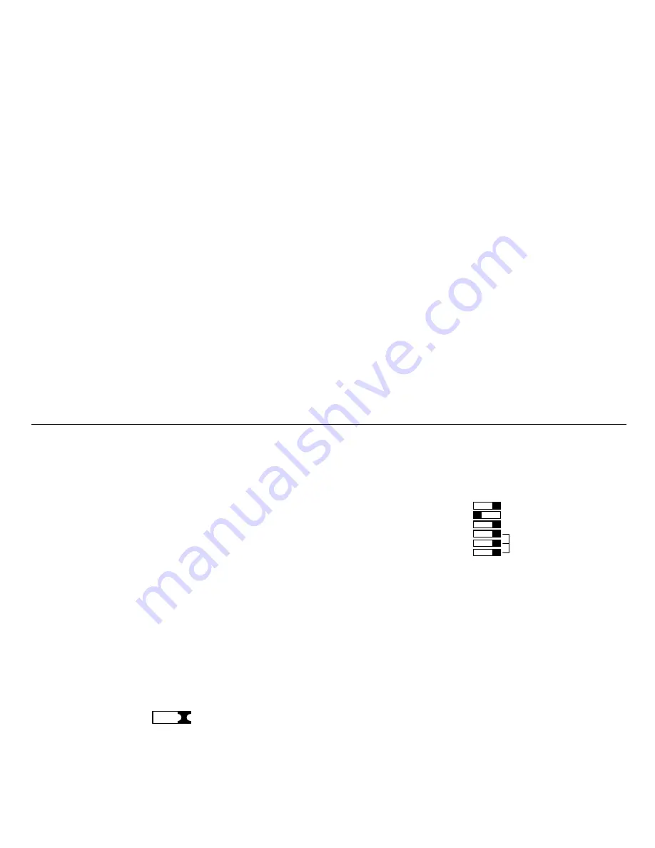
When delivered from the factory, all DIP switches on the front are
in ”off” position (pushed to the right as seen from the front). The
parameter settings are entered by changing the positions of the
individual DIP switches. This is done by inserting a pointed
instrument (e.g. a pencil) into the notch and moving the switch
into the desired position.
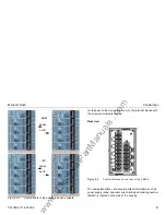
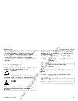
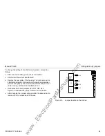
Figure 2-4
On/off position of DIP switches
2.7.1 Basic Settings Block
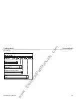
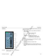
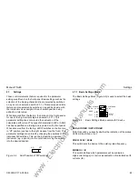
The Basic Settings Block (Figure 2-5) is used to select the basic
settings.
Figure 2-5
Basic Settings Block, example IEC device
LEDs STORED / NOT STORED
With this switch you specify whether the indication of the pickup
LEDs will be stored or not.
FREQ. 50 Hz / 60 Hz
This switch sets the device to the existing rated frequency.
MODE I>> / IE
This switch defines which parameters will be evaluated.
High-current stage (I>>) active or evaluation of calculated earth
currents (IE).
off
on
NOT STORED
60 Hz
IE
LEDs STORED
FREQ.
MODE
N INV
V INV
E INV
IEC 51
DT O/C
50/51
50 Hz
I>>
www
. ElectricalPartManuals
. com

