Manual 7SJ46
Settings
C53000-K1174-C002-4
49
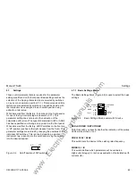
Selecting the operating mode
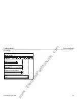
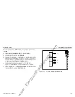
The other 3 switches are used to define the operating mode of the
protection. If you want to operate the device as definite-time
overcurrent protection (DT O/C 50/51), set switches 1 to 3 of
Basic Settings Block to switch position ”off” (see Table 2-1 on
page 50).
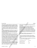
If you have selected ”DT O/C 50/51” the black printing will
apply for the parameter settings.
If you want to operate the device as an inverse-time
overcurrent protection (IEC 51 or ANSI 51), select the desired
characteristic by setting one of the switches 1 to 3 to “on” (see
Table 2-1 on page 50).
Please note that only one switch may be in “on” position!
If two or more switches are set to ”on” the red ”RUN/ERROR”
LED flashes. In this state all protection stages are deactivated.
Now select one overcurrent protection characteristic. Press the
"ENTER" key to activate the modified settings.
The "RUN/ERROR" LED now stops blinking (see Section 2.9.4).
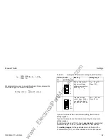
The following types of inverse overcurrent protection
characteristics can be selected:
The characteristics of the overcurrent protection can be found in
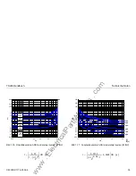
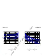
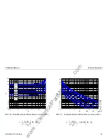
the section "Technical data" (see Figure 2-10 to Figure 2-21).
If the operating mode IEC 51 or ANSI 51 is selected, the white
marking applies for the parameter settings!
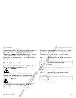
WARNING!
Changing the IE switch of the Basic Settings Block alters the
meaning of some parameters. Put the sticker that shows the new
parameter settings on top of the front panel printing!
Please note that the sticker cannot be removed again after it has
been applied!
Characteristics according to IEC Characteristics according to
ANSI
N INV
Normal inverse
M INV
Moderately inverse
V INV
Very inverse
V INV
Very inverse
E INV
Extremely inverse
E INV
Extremely inverse
www
. ElectricalPartManuals
. com

