Functions
2.12 Ground Fault Protection 64, 67N(s), 50N(s), 51N(s)
SIPROTEC, 7SJ62/64, Manual
C53000-G1140-C207-2, Release date 01.2008
239
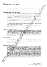
Grounded System
In grounded systems, a value is set below the minimum anticipated ground fault current. It is important to note
that 3I0 DIR (current value
RELEASE DIRECT.
) only detects the current components that are perpendicular
to the directional limit lines defined at addresses
3124
and
3125
.
COS
ϕ
is the method of measurement used,
and the correction angle is set to –45°, since the ground fault current is typically resistive-inductive (right section
of Figure 2-78 "Directional curve for cos-
ϕ
-measurement" in the functional description of the sensitive ground
fault detection).
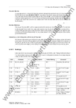
Electrical Machines
One may set the value
COS
ϕ
for the measurement method and use a correction angle of +45° for electrical
motors supplied from a busbar in an ungrounded system, since the ground current is often composed of an
overlap of the capacitive ground current from the system and the resistive current of the load resistance (left
part of Figure "Directional characteristic for cos-
ϕ
-measurement" in the functional description of the sensitive
ground fault detection).
Information on the Configuration of the Current Threshold
With devices with sensitive ground fault input, generally settings may be entered in primary values with consid-
eration given to the ratio of the applicable current transformer. However, problems related to the resolution of
the pickup currents can occur when very small settings and small nominal primary currents are involved. The
user is therefore encouraged to enter settings for the sensitive ground fault detection in secondary values.
2.12.5
Settings
Addresses which have an appended "A" can only be changed with DIGSI, under "Display Additional Settings".
The table indicates region-specific default settings. Column C (configuration) indicates the corresponding sec-
ondary nominal current of the current transformer.
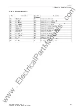
Addr.
Parameter
C
Setting Options
Default Setting
Comments
3101
Sens. Gnd Fault
OFF
ON
ON with GF log
Alarm Only
OFF
(Sensitive) Ground Fault
3102
CT Err. I1
0.001 .. 1.600 A
0.050 A
Current I1 for CT Angle
Error
3102
CT Err. I1
1A
0.05 .. 35.00 A
1.00 A
Current I1 for CT Angle
Error
5A
0.25 .. 175.00 A
5.00 A
3103
CT Err. F1
0.0 .. 5.0 °
0.0 °
CT Angle Error at I1
3104
CT Err. I2
0.001 .. 1.600 A
1.000 A
Current I2 for CT Angle
Error
3104
CT Err. I2
1A
0.05 .. 35.00 A
10.00 A
Current I2 for CT Angle
Error
5A
0.25 .. 175.00 A
50.00 A
3105
CT Err. F2
0.0 .. 5.0 °
0.0 °
CT Angle Error at I2
3106
VPH MIN
10 .. 100 V
40 V
L-Gnd Voltage of Faulted
Phase Vph Min
3107
VPH MAX
10 .. 100 V
75 V
L-Gnd Voltage of Unfault-
ed Phase Vph Max
www
. ElectricalPartManuals
. com


