Technical Data
4.1 General Device Data
SIPROTEC, 7SJ62/64, Manual
C53000-G1140-C207-2, Release date 01.2008
474
Time Synchronization Interface
4.1.5
Electrical Tests
Standards
Insulation Test
Time Synchronization
DCF 77 / IRIG B Signal
(Telegram Format IRIG-B000)
Connection for flush-mounted case
Rear panel, mounting location „A“
9-pin D-subminiature female connector
Connection for surface mounting housing
at the double-deck terminal on the case bottom
Signal Nominal Voltages
selectable 5 V, 12 V or 24 V
Test Voltage
500 V; 50 Hz
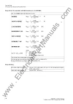
Signal Levels and Burdens
Nominal Signal Voltage
5 V
12 V
24 V
V
IHigh
6.0 V
15.8 V
31 V
V
ILow
1.0 V at
I
ILow
= 0.25 mA
1.4 V at
I
ILow
= 0.25 mA
1.9 V at
I
ILow
= 0.25 mA
I
IHigh
4.5 mA to 9.4 mA
4.5 mA to 9.3 mA
4.5 mA to 8.7 mA
R
I
890 at V
I
= 4 V
1930 at V
I
= 8.7 V
3780 at V
I
= 17 V
640 at V
I
= 6 V
1700 at V
I
= 15.8 V
3560 at V
I
= 31 V
Standards:
IEC 60255 (product standards)
ANSI/IEEE Std C37.90.0/.1/.2
UL 508
DIN 57435 Part 303
for more standards see also individual functions
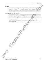
Standards:
IEC 60255-5 and IEC 60870-2-1
High Voltage Test (routine test) All circuits except
power supply, Binary Inputs, Communication Inter-
face and Time Synchronization Interfaces
2.5 kV (rms), 50 Hz
High voltage test (routine test). Auxiliary voltage
and binary inputs
3.5 kV–
High Voltage Test (routine test). Only Isolated Com-
munication and Time Synchronization Interfaces
500 V (rms), 50 Hz
Impulse Voltage Test (type test). All Circuits Except
Communication and Time Synchronization Interfac-
es, Class III
5 kV (peak value); 1.2/50 µs; 0.5 J;
3 positive and 3 negative impulses at intervals of 1 s
www
. ElectricalPartManuals
. com


