Configuration
5-11
7SJ63 Manual
C53000-G1140-C120-1
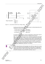
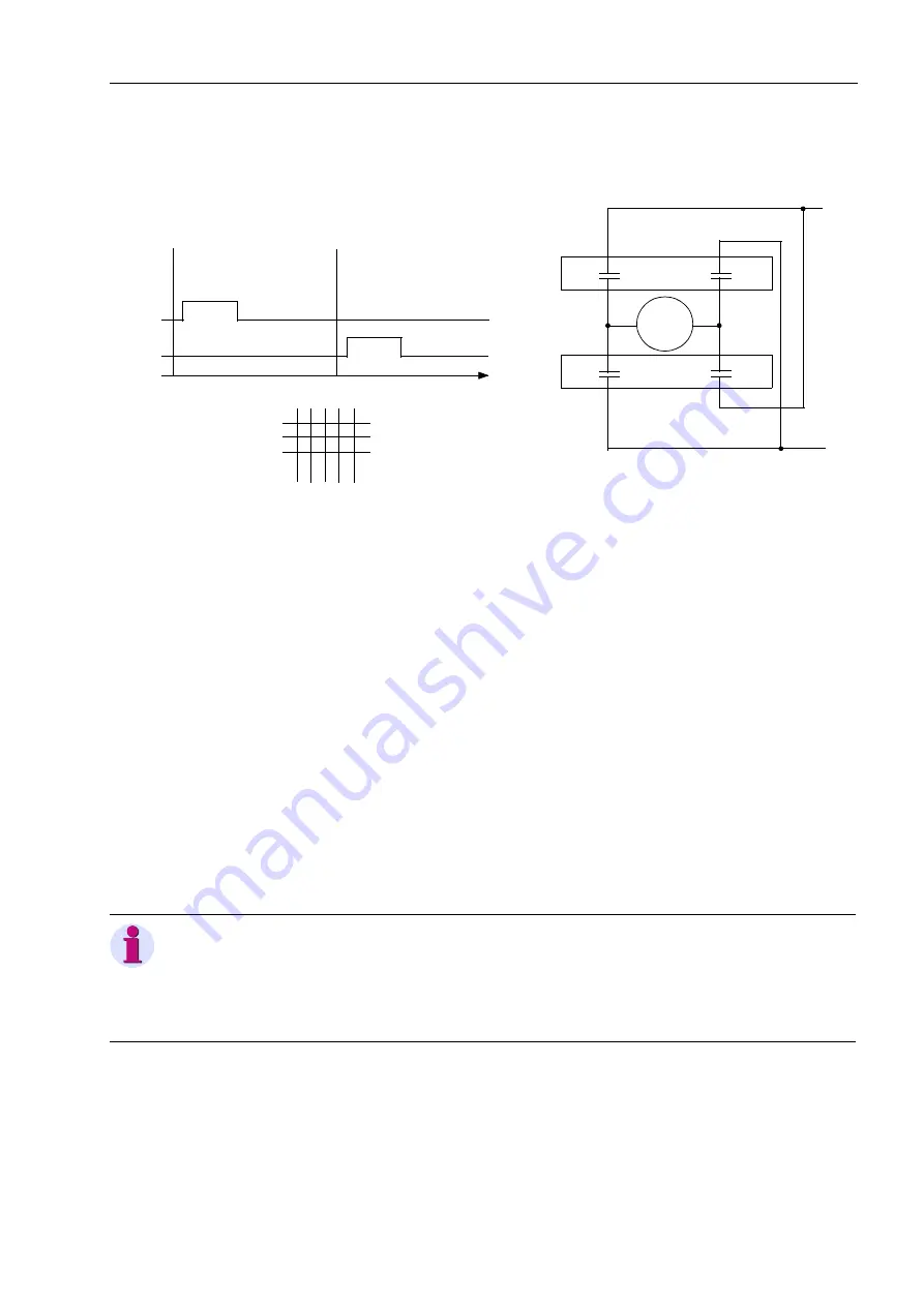
Figure 5-10
Double Command Motor Control (left/right rotation)
For the motor control in figure 5-10, the following may be configured depending on the
configuration of the switching device:
−
Through Closing Command
Left Rotation
−
Through Tripping Command
Right Rotation
−
No Command
Motor stops
The double contact output relays used for this application are blocked with respect to
each other, so only one output relay may be engaged at any given time.
When using output relays to operate a motor-controlled grounding switch and isolating
switch combination, where a common motor is used to operate both the grounding
switch and the isolating switch, consideration should be given to the fact that the same
output relays are controlled by two separate commands (the grounding command and
the isolating command). When a trip is initiated, the motor rotates in one direction to
close the ground switch, and in the opposite direction to open the isolating switch.
Therefore, one of the two commands must be negated. For this reason, command
types
%5B'
and
%5B'1
are applicable in this situation.
CLOSING
Command
C+
TRIP
Command
t
C+1
C+2
V+
V–
C–1
Relay Configuration:
C–
C–2
SD
Motor
X
BO 4
X
5
C
–
C+
Note:
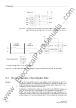
Double command breaker control (using two relays with two contacts each) is possi-
ble in the 7SJ63 family of relays with limitations. Two of the R4 ~ R7 output relays pro-
vided for motor control are used for this in models 7SJ632, 7SJ633, 7SJ635, and
7SJ636 (see Figures 5-11 and 5-12). Because of the internal connections, only relays
R5 and R6 are available. Relays R4 and R7 must remain unused.
www
. ElectricalPartManuals
. com


