Configuration
5-35
7SJ63 Manual
C53000-G1140-C120-1
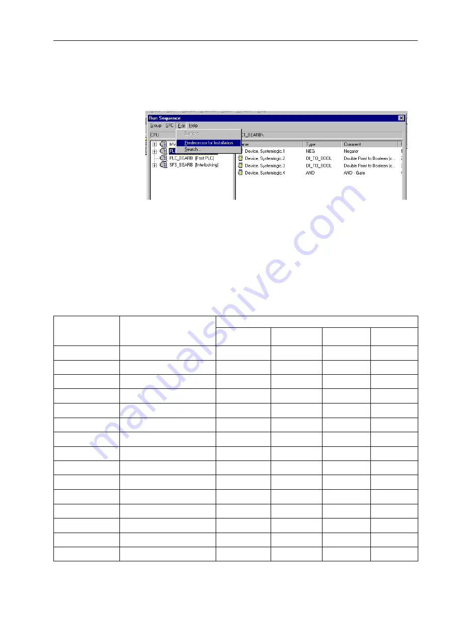
Within the Run Sequence menu, select
(GLW
, and then
3UHGHFHVVRUIRU,Q
VWDOODWLRQ
, to ensure that the function modules selected from the library will be im-
plemented into the desired task level (Figure 5-35).
Figure 5-35
Assignment of Function Modules to the Selected Task Level
The proper assignment is important for several reasons. For example, if interlocking
logic were to be set up in the measured values (Meter processing) run-time sequence
level, indications would constantly be created by the cyclical processing, filling the
buffer unnecessarily. On the other hand, the interlocking condition at the moment of a
control operation may not be processed at the right time, since meter processing is
done only every 600 ms.
Table 5-5
Selection Guide for Function Modules and Task Levels
Function Modules
Description
Task Level
MW_BEARB
Meter processing
PLC1_BEARB
Slow PLC
PLC_BEARB
Fast PLC
SFS_BEARB
Interlocking
ABSVALUE
Magnitude calculation
X
–
–
–
AND
AND-Gate
–
X
X
X
BOOL_TO_CO
Boolean to control (conversion)
–
X
X
–
BOOL_TO_DI
Boolean to Double Point
–
X
X
X
BUILD_DI
Create Double Point annunciat.
–
X
X
X
CMD_INF
Test
–
–
–
X
CONNECT
Connection
–
X
X
X
D_FF
D-Flipflop
–
X
X
X
DI_TO_BOOL
Double Point to Boolean
–
X
X
X
LIVE_ZERO
Live-zero, non linear Curve
X
–
–
–
LOWER_SETPOINT Lower limit
X
–
–
–
NAND
NAND-Gate
–
X
X
X
NEG
Negator
–
X
X
X
NOR
NOR-Gate
–
X
X
X
OR
OR-Gate
–
X
X
X
www
. ElectricalPartManuals
. com


