Functions
6-47
7SJ63 Manual
C53000-G1140-C120-1
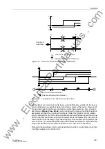
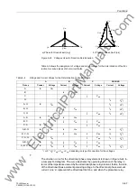
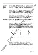
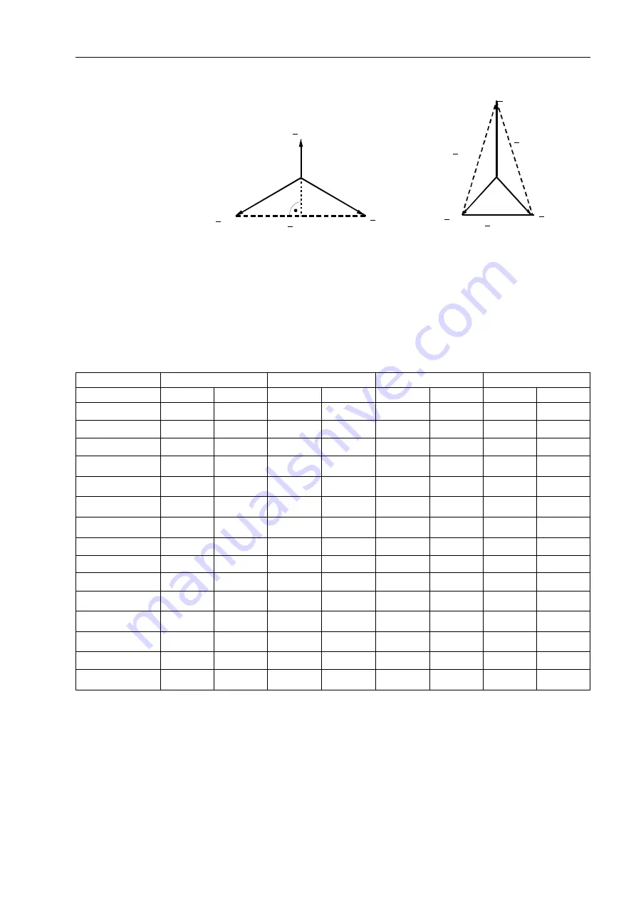
Figure 6-23
Voltages Used for Direction Determination
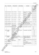
Table 6-2 shows the assignment of voltage and current values for the determination of fault di-
rection for various types of short-circuit faults.
1
) or 3 * V
0
= V
ag
+ V
bg
+ V
cg
, depending on type of connection for the voltages
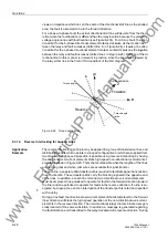
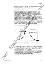
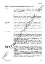
The direction curve for the directional phase relay element is shown in Figure 6-24 in
a complex R-X diagram. The curve illustrates the operating direction of the relay in
terms of the impedance viewed by the directional phase relay element, that is, the ratio
of the directional phase element polarizing voltage to the directional phase element
current. Line ‘a’ represents the directional limit line, and when the protective relay
V
CA
V
AB
V
A
V
C
V
B
V
BC
V
BC
V
C
V
B
A
V
a) Phase to Ground Fault (a-g)
b) Phase to Phase Fault (a-c)
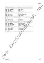
Table 6-2
Voltage and Current Values for the Determination of Fault Direction
A
B
C
GROUND
Pick up
Current
Voltage
Current
Voltage
Current
Voltage
Current
Voltage
A
Ia
V
bc
B
I
b
V
ca
C
I
c
V
ab
G
I
0
V
0
1
)
A, G
Ia
V
bc
I
0
V
0
1
)
B, G
I
b
V
ca
I
0
V
0
1
)
C, G
I
c
V
ab
I
0
V
0
1
)
A, B
Ia
V
bc
I
b
V
ca
B, C
I
b
V
ca
I
c
V
ab
C, A
Ia
V
bc
I
c
V
ab
A, B, G
Ia
V
bc
I
b
V
ca
I
0
V
0
1
)
B, C, G
I
b
V
ca
I
c
V
ab
I
0
V
0
1
)
C, A, G
Ia
V
bc
I
c
V
ab
I
0
V
0
1
)
A, B, C
Ia
V
bc
I
b
V
ca
I
c
V
ab
A, B, C, G
Ia
V
bc
I
b
V
ca
I
c
V
ab
I
0
V
0
1
)
www
. ElectricalPartManuals
. com

