Functions
6-69
7SJ63 Manual
C53000-G1140-C120-1
6.5
Inrush Restraint
General
When the 7SJ63 relay is installed to protect a power transformer, large magnetizing
inrush currents will flow when the transformer is energized. These inrush currents may
be several times the nominal transformer current, and, depending on the transformer
size and design, may last from several milliseconds to several seconds.
Although pickup of the relay elements is based only on the fundamental harmonic
component of the measured currents, false device pickup due to inrush is still a poten-
tial problem since, depending on the transformer size and design, the fundamental
harmonic comprises a large component of the inrush current.
6.5.1
Description of Inrush Restraint
Principle
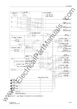
The 7SJ63 features an integrated inrush restraint function that may be utilized when
the device is installed at or near a transformer. It supervises the “normal” tripping of all
directional and non-directional overcurrent relay elements with the exception of the
50-2, 50N-2, 67-2 and 67N-2 relay elements. For example, when a transformer is en-
ergized the current levels may exceed the normal pickup of the overcurrent elements
set in the device. If inrush conditions are identified (the 2nd harmonic content of cur-
rent exceeds the value of setting at address
QG+$5021,&
), special inrush
messages are created within the device that will block tripping of the overcurrent ele-
ments. Note, that only the tripping elements are affected by harmonic inrush detection,
the pickup values and corresponding timers continue to operate normally. If inrush
conditions are still present after the tripping time delay has elapsed, a corresponding
message is displayed and recorded, but the overcurrent tripping is blocked. (see Fig-
ures 6-12, 6-13, and 6-22).
Inrush current contains a relatively large second harmonic component which is nearly
absent during a short-circuit fault. Inrush current detection, therefore, is based on the
evaluation of the second harmonic component present during inrush conditions. For
frequency analysis, digital filters are used to conduct a Fourier analysis of all three
phase currents and the ground current. As soon as the second harmonic component
of the current flowing in a specific phase or ground relay element exceeds a set value,
tripping is blocked for that element (does not apply to 50-2, 50N-2, 67-2, and 67N-2
elements). Since quantitative analysis of the harmonic components of the current flow-
ing through a specific relay element cannot be completed until a full cycle of inrush cur-
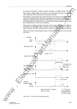
rent has been measured, inrush restraint blocking, and the associated inrush detec-
tion message, is automatically delayed by one cycle. It is important to note, however,
that the tripping time delays associated with the relay elements are started immediate-
ly after pickup of the relay element, even if the inrush conditions are detected. If inrush
blocking drops out during the time delay, tripping will occur when the time delay of the
element elapses. If inrush blocking drops out after the time delay has elapsed, tripping
will occur immediately. Therefore, utilization of the inrush restraint feature will not re-
sult in any additional tripping delays. If a relay element drops out during inrush block-
ing, the associated time delay will reset.
Cross Blocking
Since inrush restraint operates individually for each phase, inrush restraint will not
block tripping in situations where a power transformer is energized into a single-phase
fault and inrush currents are detected on the unfaulted phases. This feature provides
maximum protection, however, inrush restraint can be configured to allow inrush de-
tection on one phase to block tripping by the elements associated with the other phas-
www
. ElectricalPartManuals
. com

