Functions
6-70
7SJ63 Manual
C53000-G1140-C120-1
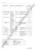
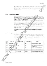
es. This is referred to as cross-blocking and can be enabled at address
. Inrush
currents flowing in the ground path will not cross-block tripping by the phase elements.
The cross-blocking function may also be limited to a particular time interval, which can
be set at address
. After expiration of this time interval, the cross-blocking func-
tion will be disabled.
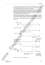
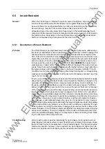
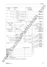
Figure 6-31
Logic Diagram for Inrush Restraint
12
<(6
“1“
A
φ
I
1/2 ac cycle
a
b
c
a > b
⋅
c
&
a
b
a < b
&
A
φ
67-1 PU
A
φ
67-TOC PU
1 ac cycle
or
Ia InRush PU
or
or
or
&
&
&
&
Inrush Recog.
50-1
Inrush Recog.
50N-1
Inrush Recog.
51
Inrush Recog.
51N
Inrush Recog. 50-1
Inrush Recog. 67-TOC
or
&
&
S
R
Q
InrushCrossBlck
2))
21
“1“
,1586+5(67
>BLOCK InRushPh
Measurement/Logic
InRush PhBLOCKED
InRush OFF
or
Ib InRush PU
Ic InRush PU
Gnd InRush PU
or
A
φ
50-1 PU
A
φ
51 PU
1 ac cycle
or
or
or
&
&
&
Inrush Recog.
67-1
Inrush Recog.
67N-1
Inrush Recog.
TOC
&
Inrush Recog.
67N-TOC
Inrush Recog. 67-1
Inrush Recog. 51
F# 7565
F# 7566
F# 7567
F# 7564
F# 7563
F# 7557
F# 7556
T
0
QG+$5021,&
,0D[
A
φ
2nd Harmonic
&5266%/2&.
&5266%/.7,0(5
Inrush Detection for Phase
and Ground Faults (50-
1,50N-1, 51-1, 51N-1, 51N-
TOC, 67-1, 67-TOC, 67N-1,
67N-TOC)
www
. ElectricalPartManuals
. com

