Installation and Commissioning
8-4
7SJ63 Manual
C53000-G1140-C120-1
Rack Mounting
For the
1
/
2
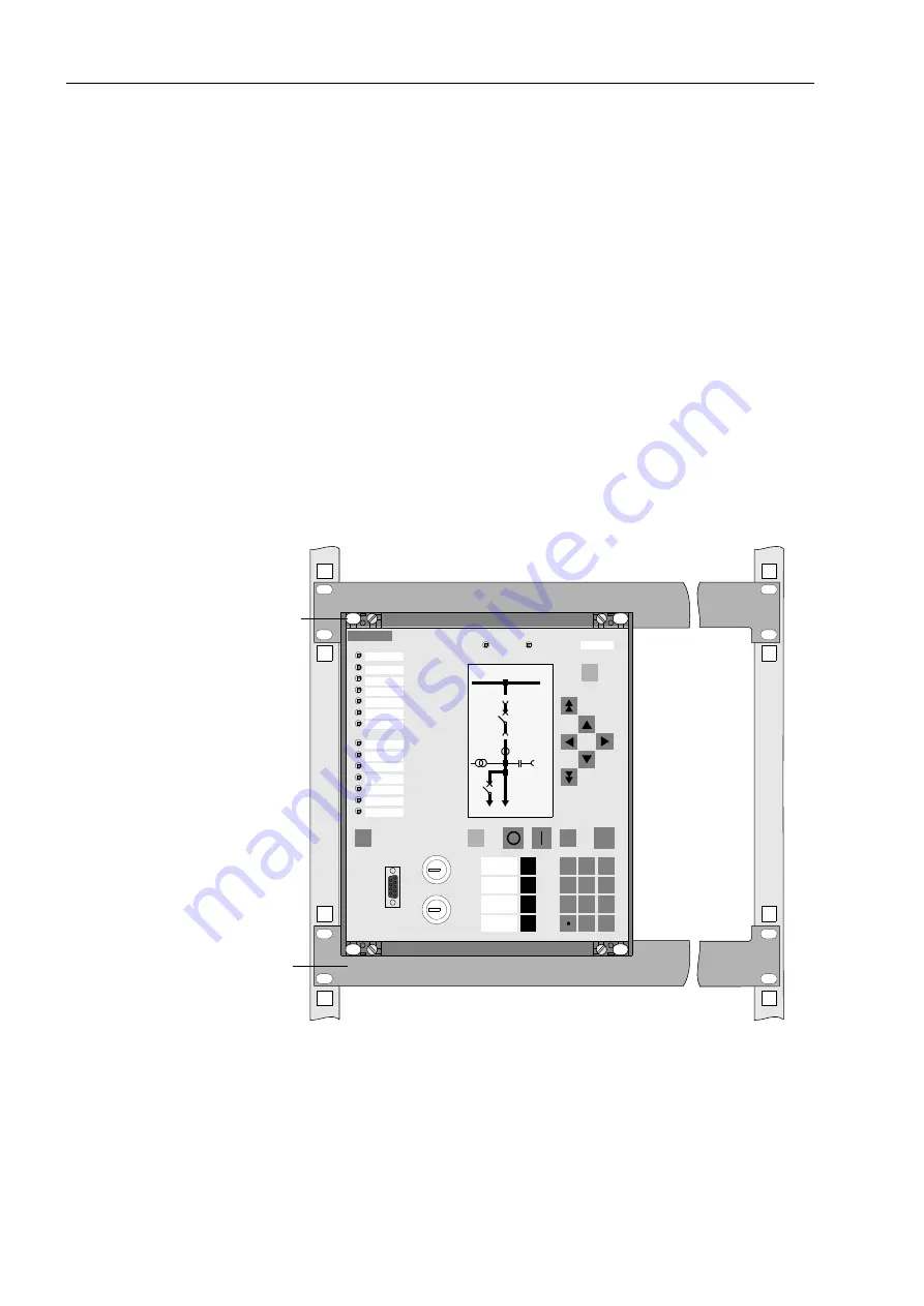
size housing shown in Figure 8-3, four covers and four fastening holes are
provided. On a device in full size housing there are six covers and six fastening holes,
as shown in Figure 8-4.
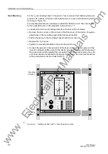
Two mounting brackets are necessary to install the 7SJ63 in a rack. The order number
for the brackets is given in the Appendix, Sub-section A.1.1.
q
Loosely screw the two mounting brackets in the rack with four screws.
q
Remove the four covers on the corners of the front cover of the device. Four elon-
gated holes in the mounting angle strips become accessible.
q
Fasten the device to the mounting brackets with four screws.
q
Replace the four covers.
q
Tighten the mounting brackets to the rack using 8 screws.
q
Connect the ground on the rear plate of the device to the protective ground of the
rack. Use at least one M4 screw for the device ground. The cross-sectional area of
the ground wire must be greater than or equal to the cross-sectional area of any oth-
er control conductor connected to the device. Furthermore, the cross-sectional area
of the ground wire must be at least AWG 13.
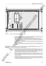
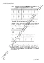
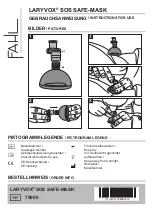
Figure 8-3
Installing a 7SJ63 with
1
/
2
Size Housing in a Rack
Mounting
Mounting
Bracket
Bracket
SIEMENS
SIPROTEC
1
2
6
3
+/-
0
5
4
7
8
9
PICKUP A
PICKUP B
TRIP
PICKUP B
PICKUP GND
PROT ENABLE
CB OPEN
CB CLOSED
T.C. FAIL
7SJ63
RUN
ERROR
MENU
ESC
LED
CTRL
ENTER
F4
F1
F2
F3
Fault Data
Meter
Breaker
Open
Remote
Normal
Local
Test
Default Display
Fault Location With F4
21 kV
1000 A
Breaker
Closed
www
. ElectricalPartManuals
. com

