Installation and Commissioning
8-24
7SJ63 Manual
C53000-G1140-C120-1
sured-values supervision elements in the device should pick up. If an element detects
a problem, the relevant condition can be viewed in the Event Log. If current summation
errors occur, then check the matching factors. See Sub-section 6.17.2.1.
Messages from the symmetry monitoring could occur because there actually are
asymmetrical conditions in the network. If these asymmetrical conditions are normal
service conditions, the corresponding monitoring functions should be made less sen-
sitive. See Sub-section 6.17.2.1.
Current and
Voltage Values
Currents and voltages can be seen in the display field on the front of the device under
0HDVXUHPHQW
. The quantities can also be viewed under
0HDVXUHPHQW
in the
DIGSI
®
4 window. The currents and voltages displayed by the device can be com-
pared to the quantities measured by an independent source.
Phase Rotation
The actual phase rotation of the voltages must correspond to the setting under Ad-
dress
3+$6(6(4
in
36\WHP'DWD
; otherwise, an alarm message occurs.
If the alarm occurs, then the phase sequence of the measured quantities should be
checked, and the proper corrections made.
Voltage
Transformer
Test Switches or
Circuit Breakers
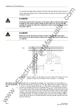
Remove voltage to the device by opening the test switches, fuses, or circuit breaker.
Under the Measurement menu, the voltage readings should be close to zero (minimal
voltage values are insignificant).
If a miniature circuit breaker (MCB) is in the VT circuits and its auxiliary contact is con-
nected to the 7SJ, the corresponding annunciations should be read from the log buff-
ers to verify connections and settings when the MCB is tripped.
When the voltage on the binary input connected to this auxiliary contact is removed,
the message “
!)$,/)(('(5
(or
%86
)
9721
” should appear in the Event Log. When
the voltage is restored, the message “>FAIL FEEDER (or BUS) VT OFF” should occur.
If one of these messages does not appear, then the connections and the configuration
settings should be checked. If the ON and OFF messages are exchanged, then the
breaker auxiliary contact type should be checked and corrected if necessary (refer to
Sub-section 5.2).
8.3.2
Directional Testing With Load Current
Load Current
≥
[10% I
N
]
This test may cause the trip outputs of the 7SJ63 to close. If tripping of primary equip-
ment is undesirable, disconnect the trip contacts of the 7SJ63; however, adequate
backup protection should be available if 7SJ63 tripping is defeated.
The connections of the current and voltage transformers are checked using load cur-
rent on the protected line or equipment. The secondary load current must be at least
[0.10 · I
N
]. The load current should be in-phase or lagging the voltage (resistive or re-
sistive-inductive load). The direction of the load current must be known. If there is a
doubt, network loops should be opened or other action taken to guarantee the direc-
tion of the load current.
The 67-TOC element is used to generate directional messages. The pickup threshold
of 67-TOC, approximately [1.1 · Address
²72&3,&.83
], must be reduced
so that the available load current causes a continuous pickup of the element. The di-
rection reported in the messages must correspond to the actual power flow. While per-
forming this test and interpreting the results, be careful that the “
)RUZDUG
” direction
www
. ElectricalPartManuals
. com

