Hardware and Connections
2-16
7SJ63 Manual
C53000-G1140-C120-1
2.2
Version of 7SJ63 for Panel Surface-Mounting
The numerical, multi-functional SIPROTEC
®
4 7SJ63 for panel surface-mounting is a
sealed device in a 7XP20 case, which again is installed in a housing with optional siz-
es of
1
/
2
or
1
/
1
(based on 19 inches).
2.2.1
Construction
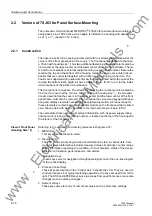
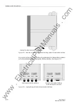
The case is inserted in a housing and secured with four screws that are located at the
corners of the front panel behind the covers. The front panel is attached to the case.
A 7SJ63 with housing size
1
/
1
has two additional fastening screws that are located be-
hind covers at the upper center and the lower center of the front panel frame. The ter-
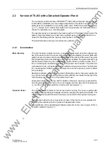
minals for connections to external equipment are grouped into two blocks that are fas-
tened to the top and the bottom of the housing. Inside the device are printed circuit
boards that are connected together with a ribbon-cable with plug connectors. The
boards are supported with guide rails of mats that are mounted within the case at the
top and the bottom. Each guide rail has a visible number, from 1 to 42, for the instal-
lation locations of the printed circuit boards.
The front panel is removable. The screws for removing the component are located be-
hind the four covers at the corners. For a 7SJ63 with housing size
1
/
1
, the two addi-
tional screws behind the covers in the upper center and the lower center of the front
panel frame must also be removed. The front panel has a covered keypad with oper-
ating and display elements necessary for equipment operation. All connections for
these elements are combined into an adapter module on the front panel that is linked
via a ribbon-cable with plug connectors to the internal processor board (CPU).
The nameplate sticker, showing important information such as power supply rating,
nominal current rating, and ordering number, is located on the top of the housing and
the interior of the front panel.
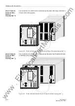
View of Front Panel
(Housing Size
1
/
2
)
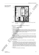
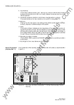
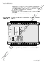
Referring to the operating and display elements in Diagram 2-16:
1. MENU Key
This key activates the main menu.
2. Display (LCD)
The LCD shows processing and device information as text in various lists. Com-
monly displayed information includes measured values (metering), counter values,
binary information regarding the condition of circuit breakers, status of the device,
protection information, general reports, and alarms.
3. Navigation Keys
These keys serve for navigation through operating menus or the one-line diagram
of the control display.
4. Process Control Keys
These keys are located on the “Control Axis” beneath the LCD. They are used to
control processes. For typical switching operations, the keys are used from left to
right. The ESC and ENTER keys serve to escape from specific menues or execute
changes (such as setting changes).
5. Numerical Keys
These keys serve for entry of numerical values, such as protective settings.
www
. ElectricalPartManuals
. com


