Technical Data
10-22
7SJ63 Manual
C53000-G1140-C120-1
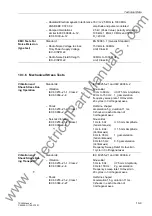
Dropout Threshold
approx. 1.05 · I
Nsp
for I
Nsp
> 50 mA
Measurement Tolerance
2 % of setting value or 1 mA
Operating Time Tolerance in the
7% of reference value for 2
≤
I/I
Nsp
≤
20
Linear Range
+ 2% current tolerance, or 70 ms
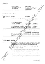
Influencing Vari-
ables
Power supply direct voltage in range
0.8
≤
V
PS
/ V
PS nominal
≤
1.15
1 %
Temperatur in range
23º F
≤
ϑ
amb
≤
131º F
0.06% /10º F
Frequency in range
0.95
≤
f/f
N
≤
1.05
1 %
Harmonic currents
– Up to 10 % 3
rd
Harmonic
1 %
– Up to 10 % 5
th
Harmonic
1 %
Note:
For the purpose of high sensitivity, the linear range of the measuring input for
the sensitive ground fault acquisition is from 0.003 A to 1.6 A. For currents greater than
1.6 A, this function drops out!
The set times are pure delay times for the definite time characteristic.
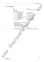
Direction Determi-
nation for All Types
of Ground Faults
Direction Measurement
– I
G
and V
G
measured (ground quantities)
– 3I
0
and 3V
0
calculated
Measuring Principle
Real/reactive power measurement
Measuring Enable I
Release direct. element
0.003 A to 1.200 A (increments 0.001A)
Current component
perpendicular (90º) to
Direction Phasor)
Dropout/Pickup (ratio)
approx. 0.80
Measuring Method
cos
ϕ
and sin
ϕ
Direction Phasor
- 45.0° to +45.0°
(increments 0.1°)
Dropout Delay T
Reset Delay
1 s to 60 s
(increments 1 s)
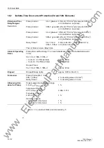
Angle correction for cable converter in 2 operating points F1/
I
1 and F2/
I
2:
(for resonant-grounded system)
Angle correction F1, F2
0.0° to 5.0°
(increments 0.1°)
Currents
I
1,
I
2
0.003 A to 1.600 A (increments 0.001A)
Measurement Tolerance
2 % of setting value or 1 mA
Angle Tolerance
3°
Note:
To achieve high sensitivity, the design of the measuring input for sensitive
ground fault acquisition is such that the linear range is from 0.003 A to 1.6 A. For cur-
rents greater than 1.6 A, correct directionality can no longer be guaranteed.
www
. ElectricalPartManuals
. com


