Appendix
A-29
7SJ63 Manual
C53000-G1140-C120-1
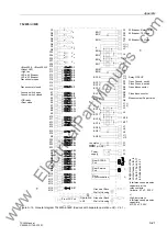
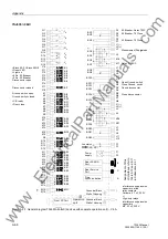
7SJ632
∗
–
∗
B
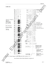
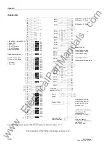
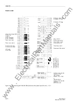
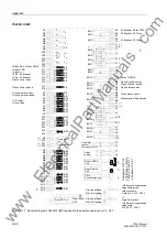
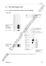
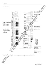
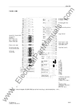
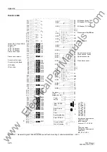
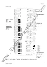
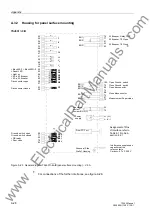
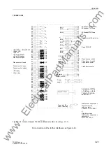
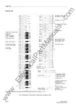
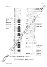
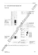
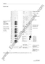
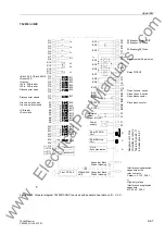
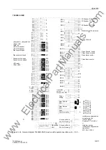
Figure A-24 General diagram 7SJ632
∗
–
∗
B (panel surface mounting) – V4.0 –
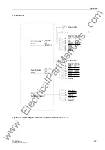
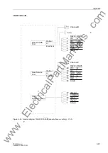
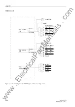
For connections of the further interfaces see figure A-26.
25
50
22
47
24
49
23
48
19
44
21
20
46
83
59
55
80
81
82
58
57
56
84
60
61
62
87
63
85
88
86
64
89
90
66
65
91
67
96
71
70
94
95
53
52
76
77
51
L+ (V+)
L– (V–)
( )
~
+
-
13
38
14
39
40
100
75
99
74
98
73
97
72
11 (–)
36 (+)
10
35
12
37
54
79
Power
Ground at Side
supply
Wall of Housing
Front PC Port
Interference suppression
capacitors at the
Ceramic, 4.7 nF, 250 V
*
)
relay contacts,
Interference suppression
capacitors
MP, 22 nF, 250 V
High-duty relays
I
A
3I
0
I
B
I
C
V
c
V
a
BI7
V
b
BI1
BI2
BI4
BI5
BI6
BI3
BI8
BI9
BI11
BI12
BI13
BI14
BI10
BI15
BI16
BI17
BI19
BI18
BI20
BI21
BI22
BI24
BI23
BO3
BO1
BO2
BO11
BO12
BO13
BO4
BO5
BO6
BO7
*
)
BO8
BO9
BO10
BO14
BO15
Live status
contact
Jumper (NO, NC)
>Block 50-2, >Block 50N-2
>Reset LED
>Light on
>52-b, 52 Breaker
>52-a, 52 Breaker
Disconnector open
Disconnector closed
Ground. switch open
Ground. switch closed
>CB ready
>Door close
52 Breaker, Relay TRIP
52 Breaker, 79 Close
Open Ground. switch
Close Ground. switch
Open disconnector
Close disconnector
Measurement Supervision
52 Breaker, 79 Close
Relay PICKUP
Assignment of Pins
of Interface, refer to
Table 8-10 in Sub-
section 8.2.1
www
. ElectricalPartManuals
. com

