Functions
6-44
7SJ63 Manual
C53000-G1140-C120-1
n
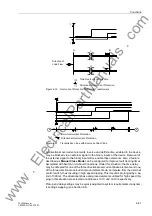
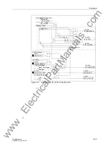
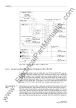
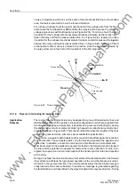
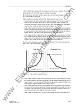
Figure 6-22
Logic Diagram for the 67-1 Relay Element
6.3.1.2
Inverse Time, Directional Overcurrent Protection (67-TOC, 67N-TOC)
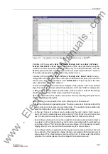
Inverse time, directional overcurrent protection, the 67-TOC and 67N-TOC relay ele-
ments may contain IEC characteristic curves or ANSI characteristic curves depending
on the model ordered. A user-specified curve may also be applied to the inverse time,
directional overcurrent relay elements. The curves and associated formulas are given
in Technical Specifications (Figures 10-1 to 10-3 in Section 10.3). During configuration
of the 67-TOC and 67N-TOC characteristic curves, the definite time directional relay
elements (67-2, 67-1, 67N-2, and 67N-1) are enabled (see Subsection 6.3.1.1).
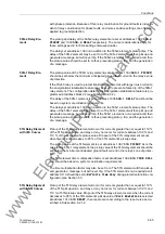
Pickup and Trip-
ping
Each phase and ground current is separately compared with the pickup values of the
67-TOC and 67N-TOC relay elements. When the currents in the 67-TOC and 67N-
TOC relay elements exceed the corresponding pickup value by a factor of 1.1, the el-
ement picks up and a message is reported. If the inrush restraint feature is being uti-
lized (see Section 6.5), then the message reported is dependent on whether or not an
inrush condition exists
.
Pickup of a 67-TOC or 67N-TOC relay element is based on the
rms value of the fundamental harmonic
.
When the 67-TOC and 67N-TOC elements
0$18$/&/26(02'(
)&772&
79 67-1 Block
or
LQVW
,QDFWLYH
“1“
LQVW
Manual Close
&
A
φ
67-1 PU
&
T
0
or
or
or
$
%
&
67-1 TRIP
67-1 picked up
or
72&LQVW
67-1 TimeOut
21
2))
“1“
>BLOCK 67-1
>BLK 67/67-TOC
67 BLOCKED
or
Phase Measurement
67/67-TOC OFF
or
67-1 BLOCKED
)RUZDUG
”1“
5HYHUVH
Phase A forward
Phase A reverse
Direction Determination
8QGHILQHG
67-1InRush PU
F# 2665
F# 7559
F# 2660
F# 2664
F# 2628
F# 2632
F# 2637
F# 2652
F# 2621
F# 2604
F# 2651
&
&
&
Inrush Recognition (see Figure 6-31)
On/Off
www
. ElectricalPartManuals
. com

