Functions
6-114
7SJ63 Manual
C53000-G1140-C120-1
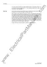
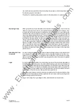
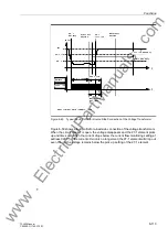
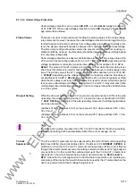
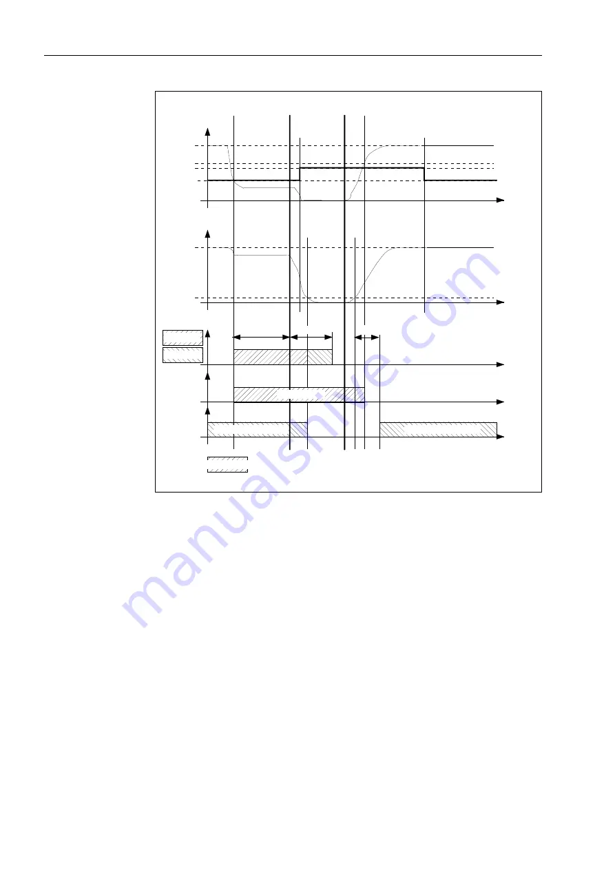
Figure 6-50
Typical Fault Profile for Load Side Connection of the Voltage Transformers
The instant after a circuit breaker is closed, the load side voltage begins to increase
and current begins to flow through the circuit breaker. To ensure that the 27-1 element
does not pickup, the element remains dropped out for a short period of time (about
20ms) until both the current flowing through the circuit breaker and the load side volt-
age stabilize. It is important to understand, however, that if a low voltage condition ex-
ists on the load after the circuit breaker is closed (i.e. a fault exists on the load side of
the circuit breaker), pickup of the 27-1 element will be delayed by 20 ms.
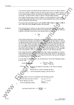
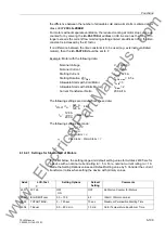
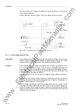
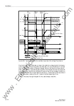
Figure 6-51 shows the logic diagram for the undervoltage protection.
Un
U< Rf
t
U(t)
In
t
I(t)
AUS
Befehl
EIN
Befehl
t
LS I >
U< AK
U<
TU <
T AUSKOM
Auslösung
Anregung
Anregeschwelle
Schwelle Stromkriterium
Anregung = Anregung U< und Stromkriterium erfüllt
t
t
Stomkriterium erfüllt
20 ms
Anregung
U<
Anrege-
rückfall
U<
Anregung U<
T AUSKOM = Mindestauskommandozeit
Rückfallschwelle
Stomkriterium erfüllt
20 ms
Pickup
Drop Out
27-1 Pickup
Closing
Signal
27-1
Drop Out
Tripping
Signal
27-1
Pickup
Drop Out Setting
Pickup Setting
Current Flow Monitoring
Setting
Current Criterion Met
Current Criterion Met
Pickup
27-1 Pickup and Current Criterion Met
Minimum Command Time
T
MIN COM
T
MIN COM
V(t)
Vn
27-1 PU
27-1 DO
Addr. 0212
27 Delay
www
. ElectricalPartManuals
. com

