'(& )( )'& &) ( &!& ")& &$(( $#
Ć
%&( $# #)" &&#$
6 - 53
Siemens AG
⋅
May 1998
6.5.3.3 Check zone
The bus-section specific protection must have a highĆ
er setting than the check zone, so that the check
zone supervision picks up before the bus-section
specific protection.
Example:
The supervision for the check zone is to be checked
with diff-current limit
I
> DIFsup : CZ
(
DA 6306/ZE
) = 0.2
I
/
I
no.
The time T-DIFF-SUP(
DA
6304/ZE
) should be set to 2.0 s. The setting for the
bus-section specific protection
I
> DIFsup : BZ (
DA
6305/ZE
) could then be 0.8
I
/
I
no
.
Settings:
D
DIFF.SUPERV set to "active";
DA 6303/ZE
D
I
> DIFsup:BZ = 0.80
I
/
I
no
;
DA 6305/ZE
D
I
> DIFsup:CZ = 0.20
I
/
I
no
;
DA 6306/ZE
D
T-DIFF-SUP= 2 s;
DA 6304/ZE
Test steps:
a) Checking pick-up limit and time delay
1. The current in feeder 1 is slowly increased until
the supervision of the check zone picks up. The
measured current must correspond to the set curĆ
rent (
DA 6306/ZE
).
2. Time measurement is performed as in test step 5.
of chapter 6.5.3.2.
b) Checking the blocking
1. When the diff-supervision of the check zone picks
up, the protection can be blocked (
DA 6308/ZE
) or
an alarm can be issued DIFF SUPCZ = alarm only
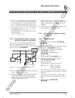
2. Bays 1 and 2 are connected to the same bus.
3. The current in feeder 1 is slowly increased until
the supervision of the check zone picks up.
4. In feeder 2, a current of 4 x
I
N
is injected. If paĆ
rameter DIFF SUPCZ (
DA 6308/ZE
) was set to
"block", then no trip commands are issued.
6.5.4
Testing the pick-up values for controlled
tripping
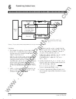
6.5.4.1 Test set-up
(as in chapter 6.5.2.1)
6.5.4.2 Test steps
Settings:
The overcurrent limit for tripping should be checked
for two feeders "
I
> TRIP".
Settings:
D
In order to prevent the diff-current supervision
from blocking the protection during testing, it must
be turned off, DIFF SUPERV (
DA 6303/ZE
).
D
The differential current limits for the bus-section
specific protection
I
>DIFF:BZ (
DA 6102/ZE
) and
for the check zone
I
>DIFF:CZ(
DA 6104/ZE
) are
both set to 1.0
I
/
I
no
.
D
The overcurrent limit for bay 1 (
DA 65XX
) is set
to 2.0
I
/
I
no
and for bay 2 (
DA 65YY
) to 0.
Test steps:
1. Bays 1 and 2 are connected to the same busbar
(by simulation of isolator status).
2. The current in bay 1 is slowly increased via the
test set. When reaching approximately 1 x
I
N
bay
unit 2 must issue a trip command, because the
overcurrent limit for this bay was set to 0. Bay unit
2 must issue a trip command at 2 x
I
N
.
www
. ElectricalPartManuals
. com
Summary of Contents for SIPROTEC 7SS52
Page 1: ... w w w E l e c t r i c a l P a r t M a n u a l s c o m ...
Page 2: ...w w w E l e c t r i c a l P a r t M a n u a l s c o m ...
Page 3: ... Siemens AG 1998 w w w E l e c t r i c a l P a r t M a n u a l s c o m ...
Page 6: ... w w w E l e c t r i c a l P a r t M a n u a l s c o m ...
Page 17: ... w w w E l e c t r i c a l P a r t M a n u a l s c o m ...
Page 33: ... w w w E l e c t r i c a l P a r t M a n u a l s c o m ...
Page 34: ... w w w E l e c t r i c a l P a r t M a n u a l s c o m ...
Page 35: ... w w w E l e c t r i c a l P a r t M a n u a l s c o m ...
Page 36: ... w w w E l e c t r i c a l P a r t M a n u a l s c o m ...
Page 44: ... w w w E l e c t r i c a l P a r t M a n u a l s c o m ...
Page 166: ... w w w E l e c t r i c a l P a r t M a n u a l s c o m ...
Page 168: ... w w w E l e c t r i c a l P a r t M a n u a l s c o m ...
Page 170: ... w w w E l e c t r i c a l P a r t M a n u a l s c o m ...
Page 184: ... 1 w w w E l e c t r i c a l P a r t M a n u a l s c o m ...
Page 186: ... w w w E l e c t r i c a l P a r t M a n u a l s c o m ...
Page 202: ... 0 0 0 w w w E l e c t r i c a l P a r t M a n u a l s c o m ...
Page 206: ... X w w w E l e c t r i c a l P a r t M a n u a l s c o m ...
Page 208: ...w w w E l e c t r i c a l P a r t M a n u a l s c o m ...
Page 209: ...w w w E l e c t r i c a l P a r t M a n u a l s c o m ...
Page 210: ... w w w E l e c t r i c a l P a r t M a n u a l s c o m ...

