'(& )( )'& &) ( &!& ")& &$(( $#
Ć
%&( $# #)" &&#$
6 - 60
Siemens AG
⋅
May 1998
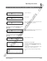
9th step:
If the station conditions permit, busbar coupling via
isolators and bus tie bay the above described tests
should be repeated in order to check the bus preferĆ
ence and the current transformer polarity in the bus
tie bay.
The protection software includes a measurement
preference with solid (isolator) bus coupling.
10th step:
Create current conditions such that the polarity of the
CTs including summation circuit (
E
) can be deterĆ
mined for each feeder.
Remarks:
For checking the polarity, a service feeder current of
at least 0.1/CT normalizing factor is required, e.g. with
n
ct
= 1, 10% of the rated current is required and with
n
ct
= 0.5, 20% of rated current is required.
If insufficient current is available for the test, then
testing of such feeders must be performed with a
primary test set.
6.6.2
Checking the connections of the circuit-
breaker failure protection initiation inĆ
puts
Subsequent to chapter 6.6.1, the tests below can be
performed:
1st step:
The supervision for the CB failure protection initiation
(
DA 6201/ZE
) must be switched off and mode of
operation "unbalance" bay-selective (
DA 66XX/ZE
)
must be selected.
2nd step:
The CB failure protection for one feeder is initiated.
The differential and stabilizing currents are displayed
under
DA 7400/ZE
. The differential current must be
equal to the feeder current with CB failure protection
initiation x normalizing factor. The stabilizing current
should be the same before and after the initiation.
This step is repeated for each feeder.
3rd step:
Following the conclusion of the test, the supervision
for the CB failure protection initiation is released
(
DA 6201/ZE
).
6.6.3
Checking the alarms and trip signals
The circuit-breaker test can be performed by current
injection or by a manual trip command , which geneĆ
rates a protection trip command or a trip command
via
DA 8200/ZE
- see chapter 6.2.5.3 or
DA 4400/FE
- see chapter 6.4.3).
Before starting the test, the corresponding feeder has
to be taken out of service. Following this step the cirĆ
cuit breaker test may be performed.
The test of the alarm relays and LEDs of the master
unit is supported by the DIGSI software. Energization
and deenergization is carried out automatically after
selection of the corresponding alarm relay number.
Optical and acoustical indicators should be used to
check the alarm relays.
6.6.4
Switching the protection into service
All setting values should be checked again, in case
they were altered during the tests. Switching the miĆ
niature circuit breakers of the DC supply OFF and ON
cancels all alarms (including operations alarms) and
the fault record memory of the master unit.
The "ready for operation" LED (green) at the ZE must
be on. The failure indication (red) must be off.
All trip signals can now be switched through. If a test
switch is available, it must be in the "service" positiĆ
on.
No alarm may be present (on the EAZ1 and EAZ2 moĆ
dule) .
www
. ElectricalPartManuals
. com
Summary of Contents for SIPROTEC 7SS52
Page 1: ... w w w E l e c t r i c a l P a r t M a n u a l s c o m ...
Page 2: ...w w w E l e c t r i c a l P a r t M a n u a l s c o m ...
Page 3: ... Siemens AG 1998 w w w E l e c t r i c a l P a r t M a n u a l s c o m ...
Page 6: ... w w w E l e c t r i c a l P a r t M a n u a l s c o m ...
Page 17: ... w w w E l e c t r i c a l P a r t M a n u a l s c o m ...
Page 33: ... w w w E l e c t r i c a l P a r t M a n u a l s c o m ...
Page 34: ... w w w E l e c t r i c a l P a r t M a n u a l s c o m ...
Page 35: ... w w w E l e c t r i c a l P a r t M a n u a l s c o m ...
Page 36: ... w w w E l e c t r i c a l P a r t M a n u a l s c o m ...
Page 44: ... w w w E l e c t r i c a l P a r t M a n u a l s c o m ...
Page 166: ... w w w E l e c t r i c a l P a r t M a n u a l s c o m ...
Page 168: ... w w w E l e c t r i c a l P a r t M a n u a l s c o m ...
Page 170: ... w w w E l e c t r i c a l P a r t M a n u a l s c o m ...
Page 184: ... 1 w w w E l e c t r i c a l P a r t M a n u a l s c o m ...
Page 186: ... w w w E l e c t r i c a l P a r t M a n u a l s c o m ...
Page 202: ... 0 0 0 w w w E l e c t r i c a l P a r t M a n u a l s c o m ...
Page 206: ... X w w w E l e c t r i c a l P a r t M a n u a l s c o m ...
Page 208: ...w w w E l e c t r i c a l P a r t M a n u a l s c o m ...
Page 209: ...w w w E l e c t r i c a l P a r t M a n u a l s c o m ...
Page 210: ... w w w E l e c t r i c a l P a r t M a n u a l s c o m ...


