'(& )( )'& &) ( &!& ")& &$(( $#
Ć
%&( $# #)" &&#$
Mode of operation
4
4 - 1
Siemens AG
⋅
May 1998
4
Mode of operation
4.1
Operation of complete unit
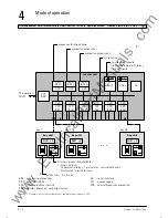
The digital busbar and breaker failure protection
7SS52 consists of compact bay units which are conĆ
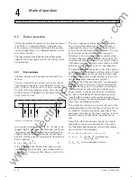
nected to the master unit by fibre-optical cables. Fig
4.1 shows the basic structure of the protection syĆ
stem.
The protection system is equipped with powerful 16
bit (bay unit) and 32 bit (master unit) microprocessors.
All tasks from aquisition of the measured values up to
the commands to the circuit breakers are exclusively
processed in a digital manner.
In the bay units the feeder or coupler currents are
measured time-synchronized, digitalized, preprocesĆ
sed and transmitted to the master unit via the fast
serial interface. The input nominal current can be 1 or
5 A depending on the main current transformer deĆ
sign. The measuring inputs are completely galvaniĆ
cally isolated and low-capacitive by transducers. SupĆ
pression of disturbances is achieved by filters which
are optimized for the measured value processing with
regard to bandwidth and processing speed.
The bay unit captures the isloator positions and bay-
related binary signals, processes functions of the
breaker failure protection and fulfills autodiagnosis
tasks.
Heavy-duty command relays take the protection syĆ
stem's trip commands directly to the circuit breakers.
Alarm relays and indications (LED; LC display) allow
event indication. In addition operational measured vaĆ
lues are displayed.
The master unit is designed as a multi-processor syĆ
stem.
The measured currents are read in from the connecĆ
ted bay units time-synchronized and are processed
together with binary information from the protection
functions (differential protection, breaker failure proĆ
tection). The master unit transmits the results of the
calculations as well as logical combinations cyclicly to
the bay units.
Freely marshallable alarm relays are provided for reĆ
mote signalling.
The master unit administers all configuration and setĆ
ting data for the busbar and breaker failure protection
functions. Communication is possible via an integraĆ
ted key-pad with LC display or via the serial interface
by means of a PC utilizing the program DIGSI. In addiĆ
tion the program can read out fault data from the proĆ
tection device and analyse it.
The master unit and bay units contain power supply
modules for a reliable power supply on different volĆ
tage levels.
www
. ElectricalPartManuals
. com
Summary of Contents for SIPROTEC 7SS52
Page 1: ... w w w E l e c t r i c a l P a r t M a n u a l s c o m ...
Page 2: ...w w w E l e c t r i c a l P a r t M a n u a l s c o m ...
Page 3: ... Siemens AG 1998 w w w E l e c t r i c a l P a r t M a n u a l s c o m ...
Page 6: ... w w w E l e c t r i c a l P a r t M a n u a l s c o m ...
Page 17: ... w w w E l e c t r i c a l P a r t M a n u a l s c o m ...
Page 33: ... w w w E l e c t r i c a l P a r t M a n u a l s c o m ...
Page 34: ... w w w E l e c t r i c a l P a r t M a n u a l s c o m ...
Page 35: ... w w w E l e c t r i c a l P a r t M a n u a l s c o m ...
Page 36: ... w w w E l e c t r i c a l P a r t M a n u a l s c o m ...
Page 44: ... w w w E l e c t r i c a l P a r t M a n u a l s c o m ...
Page 166: ... w w w E l e c t r i c a l P a r t M a n u a l s c o m ...
Page 168: ... w w w E l e c t r i c a l P a r t M a n u a l s c o m ...
Page 170: ... w w w E l e c t r i c a l P a r t M a n u a l s c o m ...
Page 184: ... 1 w w w E l e c t r i c a l P a r t M a n u a l s c o m ...
Page 186: ... w w w E l e c t r i c a l P a r t M a n u a l s c o m ...
Page 202: ... 0 0 0 w w w E l e c t r i c a l P a r t M a n u a l s c o m ...
Page 206: ... X w w w E l e c t r i c a l P a r t M a n u a l s c o m ...
Page 208: ...w w w E l e c t r i c a l P a r t M a n u a l s c o m ...
Page 209: ...w w w E l e c t r i c a l P a r t M a n u a l s c o m ...
Page 210: ... w w w E l e c t r i c a l P a r t M a n u a l s c o m ...

