'(& )( )'& &) ( &!& ")& &$(( $#
Ć
%&( $# #)" &&#$
5 - 2
Siemens AG
⋅
May 1998
5.2.1
Connection of the bay units in the
bus coupler bay
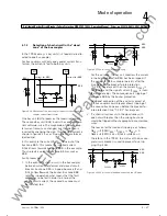
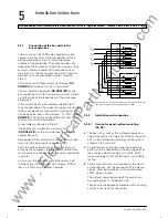
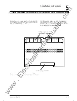
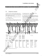
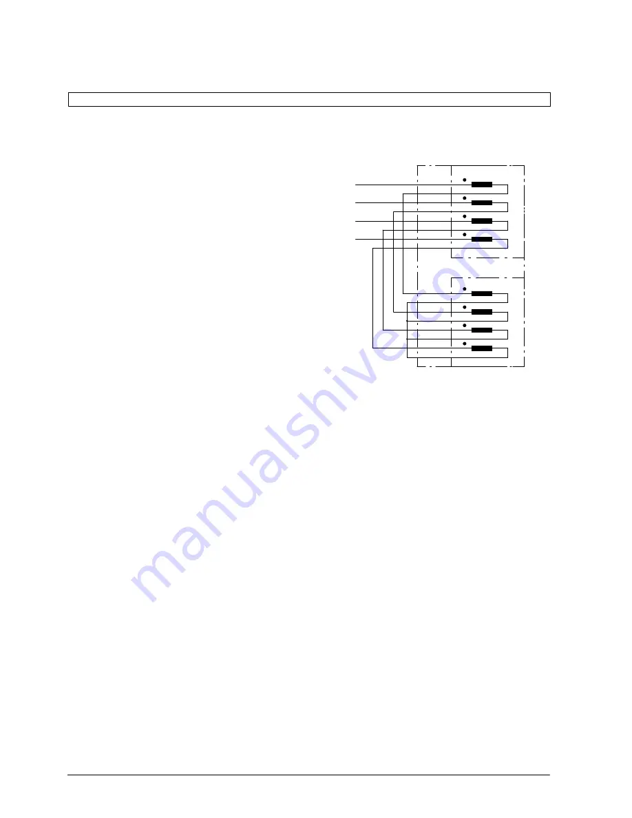
Two bay units of the 7SS52 are allocated to a bus
coupler. Both bay units are totally identical in their
design and occupy 2 bays in the configuration
scheme of the protection. The allocation does not
depend on the number of current transformers ( one
or two) in the bus coupler. With only one current
transformer in the bus coupler, the current inputs of
both bay units are connected in series. (refer to
Fig 5.1).
For the bay unit without current transformer,
DA
XX04/ZE
has to be set to "no CTexiststent".
The setting of the parameter
DA XX05/ZE
for the
bus coupler bay with the current transformer is identiĆ
cal to that one of the feeder bays of the corresponĆ
ding busbar.
If the current inputs are wired according to Fig 5.1,
then the direction of the current has to be inverted for
the bus coupler bay without current transformer. This
can be done by means of parameter "CT-POL" (
DA
XX05/ZE
). The setting will be different to that one of
the bay with current transformer.
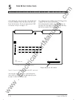
An example can be seen in Fig 5.2.
The parameter "current transformer ratio"
(
DA XX06/ZE
) has to be set identical for both bus
coupler bay units.
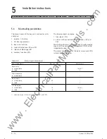
Recognition of the isolator status is carried out sepaĆ
rately via the binary inputs of each bay unit.
For the mostly used version of a bus coupler with
only one circuit breaker, the trip command and transĆ
fer trip contacts of both bay units must be connected
in parallel.
In this case, the connection of further binary input
functions (e.g. CBF initiation, CBF release, TRIP reĆ
lease, CB fail) has to be done in parallel.
8B2
8B1
7B2
7B1
6B2
6B1
5B2
5B1
L1
L2
L3
E
8B2
8B1
7B2
7B1
6B2
6B1
5B2
5B1
FE1
FE2
5.2.2
Installation and connection
5.2.2.1 Version for panel surface mounting
(FE, ZE)
D
The bay unit as well as the surface-mounted caĆ
sing of the master unit are each fitted to the panel
by 4 screws (dimension drawings can be seen in
chapters 2.6.1 and 2.6.2)
D
A solid low-ohmic and low-inductive operating
earth has to be connected to the earthing point of
the casings side-wall using a screw M4. Earth
tapes according to DIN 72333 form A are suitable
for this.
D
Screw-type terminals are provided for the electriĆ
cal connections. For the connection of the optical
signals, fibre-optical cables with pre-fabricated
FSMA plugs are used.
The surface-mounted casing of the master unit
has cable glands at the bottom side.
They ensure the degree of protection of the casing
and the strain-relief for the cables.
www
. ElectricalPartManuals
. com
Summary of Contents for SIPROTEC 7SS52
Page 1: ... w w w E l e c t r i c a l P a r t M a n u a l s c o m ...
Page 2: ...w w w E l e c t r i c a l P a r t M a n u a l s c o m ...
Page 3: ... Siemens AG 1998 w w w E l e c t r i c a l P a r t M a n u a l s c o m ...
Page 6: ... w w w E l e c t r i c a l P a r t M a n u a l s c o m ...
Page 17: ... w w w E l e c t r i c a l P a r t M a n u a l s c o m ...
Page 33: ... w w w E l e c t r i c a l P a r t M a n u a l s c o m ...
Page 34: ... w w w E l e c t r i c a l P a r t M a n u a l s c o m ...
Page 35: ... w w w E l e c t r i c a l P a r t M a n u a l s c o m ...
Page 36: ... w w w E l e c t r i c a l P a r t M a n u a l s c o m ...
Page 44: ... w w w E l e c t r i c a l P a r t M a n u a l s c o m ...
Page 166: ... w w w E l e c t r i c a l P a r t M a n u a l s c o m ...
Page 168: ... w w w E l e c t r i c a l P a r t M a n u a l s c o m ...
Page 170: ... w w w E l e c t r i c a l P a r t M a n u a l s c o m ...
Page 184: ... 1 w w w E l e c t r i c a l P a r t M a n u a l s c o m ...
Page 186: ... w w w E l e c t r i c a l P a r t M a n u a l s c o m ...
Page 202: ... 0 0 0 w w w E l e c t r i c a l P a r t M a n u a l s c o m ...
Page 206: ... X w w w E l e c t r i c a l P a r t M a n u a l s c o m ...
Page 208: ...w w w E l e c t r i c a l P a r t M a n u a l s c o m ...
Page 209: ...w w w E l e c t r i c a l P a r t M a n u a l s c o m ...
Page 210: ... w w w E l e c t r i c a l P a r t M a n u a l s c o m ...

