Busbar Protection
95
7SS52 V4 Manual
C53000-G1176-C182-3
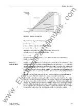
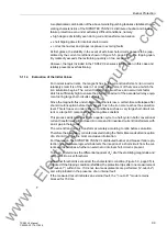
Figure 5-3 Standard characteristic
The vectorial sum I
d
as the tripping quantity
I
d
=
|
I
1
+
I
2
...
+
I
n
|
is counterbalanced by the restraining quantity I
s
I
s
=
| I
1
|
+
| I
2
| ...
+
|
I
n
|
which is the arithmetic sum of the magnitudes of each current.
The criterion for a short-circuit on the busbar is thus:
I
d
>
k
.
I
s, mod
The modified stabilizing quantity I
s, mod
is derived from I
s
and is illustrated in
Standard
characteristic
Figure 5-3, page 95 illustrates the characteristic of a stabilized (restrained) differential
protection system. In the diagram, the abscissa represents the sum I
s, mod
of the mag-
nitudes of all quantities flowing through the busbar while the vectorial sum I
d
is plotted
as the ordinate. Both axes use rated current as the unit and both have the same scale.
If a short-circuit occurs on the busbars whereby the same phase relation applies to all
infeeding currents, I
d
is equal to I
s
. The fault characteristic is a straight line inclined at
45
°
.
Any difference in phase relation of the fault currents leads to a (practically insignifi-
cant) lowering of the fault characteristic. Since in fault-free operation I
d
is
approximately zero, the x-axis may be referred to as the normal load line. The stabi-
lizing factors can be selected in a range of k
=
0.10 to 0.80 for the bus zone-specific
busbar protection or k
=
0.00 to 0.80 for the check zone. The factors are represented
as three straight lines with corresponding gradient and form the operating character-
istic. The differential protection system determines whether the total of all currents
supplied by the current transformers represents a point in the diagram above or below
the set characteristic line. If the point lies above that line, tripping is initiated.
www
. ElectricalPartManuals
. com


