Busbar Protection
105
7SS52 V4 Manual
C53000-G1176-C182-3
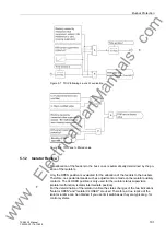
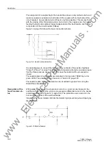
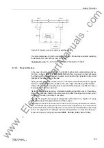
Figure 5-12 Operation of a bus coupler as switchgear bay
The protected zone ends at the current transformer. All electrical elements including
the isolators Q10 and Q20 are part of the line.
Configuration note: The dotted part must not be displayed with Digsi!
5.1.3.6
Transfer Busbars
In the case of external transformers, the transfer busbar can be protected selectively.
For this, configure
PROT TR BUS
(
5401/CU
) with
Yes
. Any case of a fault will cause
the tripping of the bypass breaker (coupler) and a transfer trip signal to trip the circuit
breaker at the remote end of the line.
During transfer operation, the line isolator in the feeder which is located on the bypass
busbar is replaced by the line isolator of the bus coupler. Monitoring of the isolator
states in the feeder and coupling bays ensures that this happens only after the bus or
feeder isolator had been opened.
Up to the final bypass operation, intermediate switching positions occur. The alloca-
tion of the respective feeder to the bus zone during this time depends on the current
transformer location (bus side or line side).
Figure 4-15, page 64 shows a plant configuration with transfer bus. Figure 5-13, page
106 summarizes the busbar allocation of the feeders.
Normally the check zone measurement does not require any isolator status informa-
tion. For checkzone measurement, the current of the coupler must be considered if a
feeder with internal current transformer is connected to the transfer busbar (see Chap-
ter 5.1.3.7, page 107) or if with external current transformers no transfer busbar pro-
tection is required (configure parameter
PROT TR BUS
(
5401/CU
) with
No
).
www
. com

