Functions
142
7SS52 V4 Manual
C53000-G1176-C182-3
5.5.1.2
Auxiliary and Reference Voltages
The bay unit processor monitors the
reference voltages of the measured value detec-
tion, as well as the supply voltages.
The protection is suspended if the voltages devi-
ate outside an allowable range; depending on the setting of the parameter
(
), the blocking is selective or complete; the deviation is reported
after
three scanning cycles “
15V-superv $00
“ (
FNo. 176.1171/CU
),
“
5V-superv $00
“ (
), “
0V-superv $00
“ (
/
CU
The auxiliary voltages in the central unit are monitored by the converters themselves.
Faults are annunciated “
15V-superv CU
“ (
), “
24V-superv CU
“
(
)
.
Failure or disconnection of the auxiliary voltage automatically
takes the affected device out of service. This status is annunciated via an NC contact.
Transient auxiliary voltage dips of
≤
50 ms will not influence the unit
Depending on the setting of the parameter
), a failure of
the auxiliary voltage in a bay unit results in a selective or complete blocking of the pro-
tection system.
5.5.1.3
Measured Value Supervision
The analog input circuits of the bay unit are cyclically monitored from the input trans-
ducers up to the digitalization. This is done by forming the current sum and executing
the following plausibility check:
∆
I
=
I
L1
+ I
L2
+ I
L3
+ I
E
Σ
|
I
|
=
|
I
L1
|
+
|
I
L2
|
+
|
I
L3
|
+
|
I
E
|
The measured value monitoring picks up if
| ∆
I
|
>
0.2 I/I
N
and
|
∆
I
|
>
k
.
Σ
|
I
|
with k
=
0.125 (stabilizing factor)
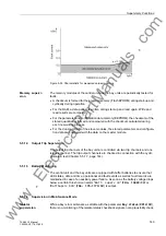
The pick-up characteristic is shown in Figure 5-33, page 143.
If the supervision detects that the measured values are not plausible, the analog
measuring circuits are assumed to be faulty, the measured value cycle is accordingly
marked and the calculation of the protection algorithms blocked for this cycle. If the
fault prevails longer than 1 s time, the protection system is selectively or completely
blocked and an annunciation "
MeasInSup $00
" (
FNo. 176.1175/CU
)
The blocking can only be reset with a warm restart (Figure 5-32, page 141).
www
. ElectricalPartManuals

