Maintenance and Repair
296
7SS52 V4 Manual
C53000-G1176-C182-3
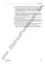
The following measures allow to locate the failure.
General
measures
If the substation is operating and the control voltage for the trip circuits of the circuit
breakers is on, the intact portion of the protection system can remain available until
the failure is eliminated.
For this purpose, set the parameter
) to
.
The protection processing remains active for all zones which are not affected by the
failure. Tripping is enabled by the check zone. As a result, the functioning of the
faulty bay is suspended (Chapter 5.5.1, page 140).
XX12/CU
to take the faulty
bay out of service. The protection function is now active again for all zones. The
faulty bay unit no longer appears in the alarm list of the central unit.
Test mode of the
SK module
To further locate the failure, switch the ZPS-SK module to test mode. The protection
processing is the same as in normal mode, but more tolerant to errors.
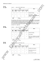
In test mode, the LEDs on the ZPS-SK module have more options for indicating
information. The LEDs are visible after opening the front panel of the central unit. One
red flashing LED per ZPS-SK module indicates that the ZPS-SK module is in test
mode. One green and three yellow LED indicate the disturbed duplex channel with the
highest channel number according to Table 8-5, page 296. A flashing greed LED
indicated that at least one duplex channel on the ZPS-SK module is faulty.
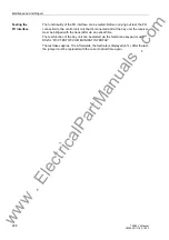
There are two ways for activating the test mode on the ZPS-SK module. The first is to
activate the test mode with the DIGSI communication software:
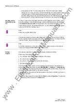
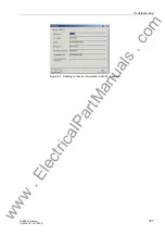
Open the central unit in the DIGSI Manager.
Note
You can retrieve a quick and clear overview of the current communication status for
the individual bay units via the Web Monitor under
SIEMENS Internal Diagnostics
→
HDLC State (see Figure 7-4, page 266).
Table 8-5
LEDs of the ZPS-SK module in SK test mode
LEDs
Status
RED
H1r
GREEN
H1g
YELLOW1
H2
YELLOW2
H3
YELLOW3
H4
⊗
⊗
⊗
⊗
⊗
⊗
⊗
⊗
⊗
o
⊗
⊗
⊗
⊗
⊗
⊗
⊗
⊗
•
•
o
•
o
•
o
•
o
•
•
•
o
o
•
•
o
o
•
•
•
•
•
o
o
o
o
no failure
Failure in channel 0, bay 1
Failure in channel 1, bay 2
Failure in channel 2, bay 3
Failure in channel 3, bay 4
Failure in channel 4, bay 5
Failure in channel 5, bay 6
Failure in channel 6, bay 7
Failure in channel 7, bay 8
o
bright
•
dark
∇
dim
⊗
flashing
www
. ElectricalPartManuals
. com


