Design and Connection System
20
7SS52 V4 Manual
C53000-G1176-C182-3
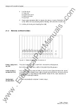
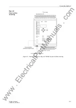
Figure 2-5 Module arrangement in the bay unit 7SS525
PFE/SVW module
In the PFE/SVW module the firmware is located and processed; it also contains the
power supply, the current transformers and the measured value acquisition function.
AFE module
The AFE module contains the alarm and trip relays.
EFE_10 module
The EFE_10 contains the binary inputs and receives indications (e.g. from isolators
and circuit breakers).
Heavy-duty
current terminals
The heavy-duty current terminals automatically short-circuit the current transformer
when the module is withdrawn.
Plug-in modules
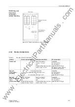
The plug-in modules are identified according to their position in a coordinate system.
The connections inside a module are numbered consecutively from left to right
(viewed from the rear), see example in Figure 2-8, page 24.
www
. ElectricalPartManuals
. com

