Bay Unit
21
7SS52 V4 Manual
C53000-G1176-C182-3
2.2.3
Design
2.2.3.1
Panel Surface Mounting
For panel surface mounting, only possible for device 7SS523, the bay units are deliv-
ered in casings type 7XP20. The front plate is hinged and can be pulled out with a
plastic tab and swung to the left for easy servicing.
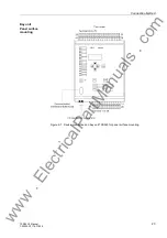
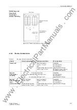
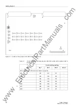
All signals including the auxiliary voltage are connected to two-tier terminals. In each
tier the terminals are numbered from left to right (Figure 2-7, page 23).
For the fiber-optic interface, 2 ST connectors are provided at the bottom of the device
next to the terminal strip.
Earthing screws are provided at the left side of the housing.
The dimensions of the housing can be in Figure 9-4, page 331.
2.2.3.2
Panel Flush Mounting or Cubicle Mounting
For panel flush mounting or cubicle mounting the bay units are delivered in casings
type 7XP20. With the bay unit 7SS523 the front plate is hinged and can be pulled out
with a plastic tab and swung to the left for easy servicing. With the bay unit 7SS525
the front plate can be removed.
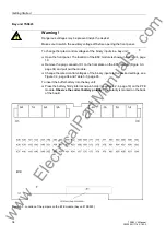
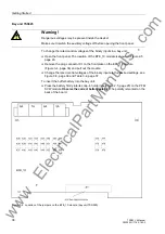
All signals including the auxiliary voltage are connected to terminal blocks on the rear
plate. For each electrical connection point, there is one screw-type and one snap-in
connector for the station wiring.
For the fiber-optic interface, 2 ST connectors are provided at the rear of the device
next to the terminal strip.
An earthing screw is provided at the back of the housing.
The dimensions of the housing can be in Figure 9-5, page 332.
www
. ElectricalPartManuals
. com


