Matching the Control Voltage for the Binary Inputs and Inserting the Buffer Battery
31
7SS52 V4 Manual
C53000-G1176-C182-3
3.3
Matching the Control Voltage for the Binary Inputs and
Inserting the Buffer Battery
Control voltage
When delivered, the binary inputs of the EAZ and D-CPU modules in the central unit,
and the EFE or EFE_10 modules in the bay units, are configured for 220 V rated con-
trol voltage.
For each binary input, different switching thresholds can be selected. This is done on
the central unit by means of 3 jumpers on the EAZ module and 4 jumpers on the D-
CPU module, and in the bay units by 3 jumpers each on the EFE or EFE_10 modules.
Central unit
To change the rated control voltages of the binary inputs in the central unit:
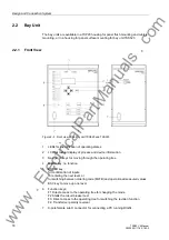
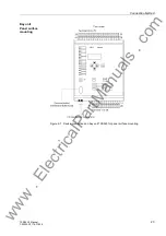
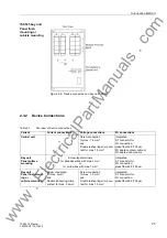
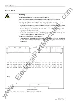
Open the front panel. The location of the EAZ and D-CPU module is shown in Fig-
ure 2-2, page 16.
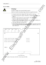
Remove the front plug connectors X3, X4, X5 on the D-CPU module
(Figure 3-2, page 33).
Press down the locking bolt of the modules at the bottom guide rail.
Use the extraction handle (included in the delivery) to pull out the module.
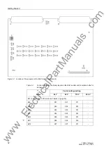
Change the rated control voltages for the binary inputs of the EAZ module as de-
sired by relocating the jumpers (shown in Figure 3-1, page 32 and Table 3-1, page
32).
Change the rated control voltages for the binary inputs of the
D-CPU module by relocating the jumpers (shown in Figure 3-2, page 33 and Table
3-2, page 33).
To insert the buffer battery into the central unit:
Press the battery firmly into its snap-in holder (see Figure 3-2, page 33) on the D-
CPU module.
Observe the correct battery polarity!
Warning!
Only one jumper may be fitted per binary input.
Warning!
Dangerous voltages may be present inside the device!
Make sure to switch the auxiliary voltage off before opening the front panel.
www
. ElectricalPartManuals
. com


