Configuration Notes
65
7SS52 V4 Manual
C53000-G1176-C182-3
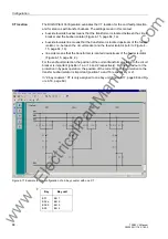
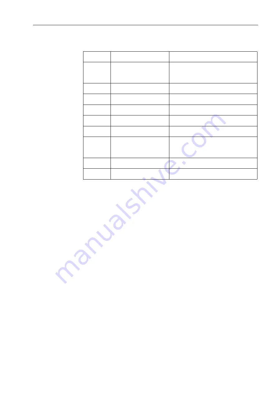
Table 4-1
Configuration for a triple busbar with transfer busbar
Bay: (XX)
Bay: Type
CT LOC
01
Feeder bay
1a) Bus side t. bus
1b) Bus side t. line
2) line side
02
2-bay coupler
Bus side t. line
03
2-bay coupler
non existent
04
2-bay coupler
Bus side t. line
05
2-bay coupler
Bus side t. line
06
Section isolator
non existent
07
Feeder bay
1a) Bus side t. bus
1b) Bus side t. line
2) line side
08
2-bay coupler
Bus side t. line
09
2-bay coupler
non existent
1a) inside current transformer (referred to Q7), in the direction of the busbar (referred to Q0)
1b) inside current transformer (referred to Q7), in the direction of the line (referred to Q0)
2) line side current transformer (referred to Q7)
www
. ElectricalPartManuals
. com


