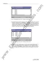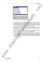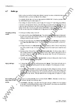
Configuration Notes
67
7SS52 V4 Manual
C53000-G1176-C182-3
Bay types
In the DIGSI Plant Configuration you may configure the feeders as 1-bay-coupler, 2-
bay-coupler, feeder bay or sectionalizer.
Reserve bays
Reserve bays may be provided for in the configuration; they may be assigned any
number that corresponds to their actual location. DIGSI configures the corresponding
bay to
not existent
, if it has been drawn in the Plant Configuration but is not assigned
in the "Bay unit allocation".
Hardware design
Depending on the size of the plant, the hardware design of the central unit can be
adapted in steps of 8 connections for bay units.
Station
configuration
One bay unit is allocated to each feeder bay and each sectionalizer. The station con-
figuration can include up to 16 bus couplers and 24 sectionalizers.
Accordingly, bus couplers may be assigned one or two bay units depending on the
number of primary components.
Bus couplers
For further explanations about connection and setting of the bus coupler bays please
refer to Chapter 7.1.3, page 258.
Isolator
Up to 5 isolators can be connected to each bay unit. Transferbus isolators must be
marked correspondingly in the Object Properties.
For each isolator one auxiliary contact for recognition of the OPEN position and one
auxiliary contact for recognition of the CLOSED position is wired to the bay unit.
The binary inputs BI1 to BI10 of bay unit 7SS523 have default allocations (refer to
Chapter A.15, page 395) which can however be changed. Bay unit 7SS525 with BI1
to BI4.
The isolators in the individual bus zones are assigned via the bus zone number.
Sectionalizing iso-
lator
Isolators 1 to 5 can be used as sectionalizing isolator too. If the bay unit has exclusive-
ly sectionalizing isolators the type "sectionalizing isolator " is assigned to the bay unit.
A maximum of 24 sectionalizers can be configured per substation.
CTs
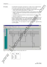
To include the transfer or combi-bus in the protection system, the CTs in the feeder
bays (Figure 4-16, page 66) must be located on the line side, and the protection func-
tion must be released in
(
5401/CU
).
www
. ElectricalPartManuals
. com


