Functions
112
7SS52 V4 Manual
C53000-G1176-C182-3
5.2
Check Zone
5.2.1
The measuring system for the check zone detects a short-circuit in all bays, regardless
of the isolator status.
In some special cases, isolator status must however be considered for the check
zone.
If the stabilizing current is calculated in the same manner as for the bus zone-specific
busbar protection, overstabilization results in multiple busbar systems. This oversta-
bilization is caused by those bays which are not connected to the faulty busbar.
To avoid overstabilization, the stabilizing current is calculated as follows:
Σ
| I
p
|
=
sum of the magnitudes of the currents which flow in the direction of the busbar
Σ
| I
n
|
=
sum of the magnitudes of the currents which flow away from the busbar
I
stab
=
lesser of the above two sums
By forming the stabilizing current in this manner, only half of the total through-flowing
load current acts as stabilizing current.
The short-circuit current does not stabilize the ”check zone” and only acts as differen-
tial current.
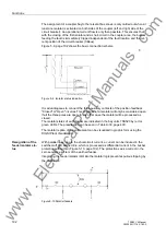
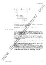
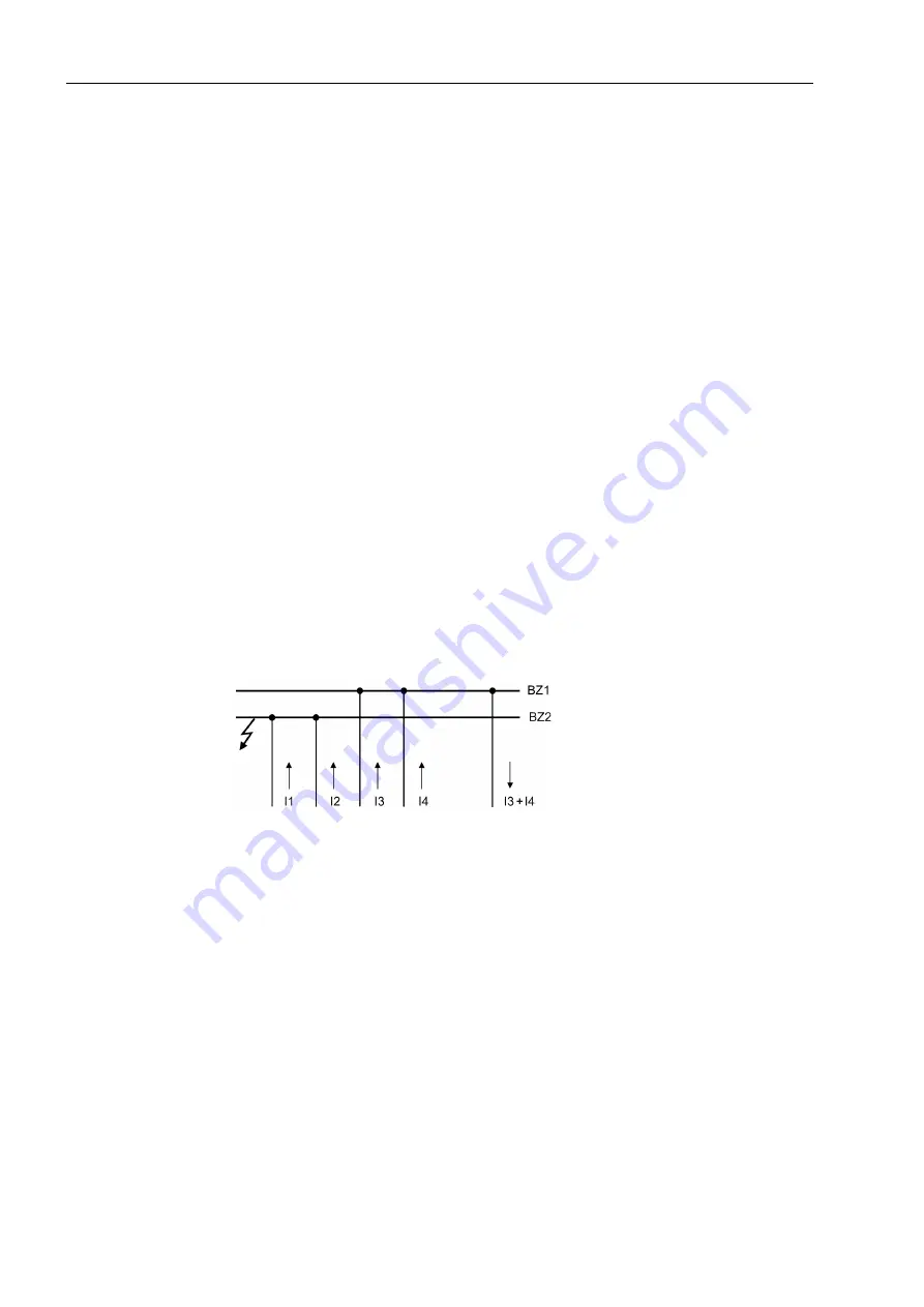
This procedure is illustrated in Figure 5-15, page 112 and in the equations below.
Figure 5-15 Treatment of the stabilizing current for the check zone
I
d
=
|
I
1
+
I
2
+
I
3
+
I
4
−
I
3
−
I
4
|
=
|
I
1
+
I
2
|
Stabilizing current without special treatment:
I
s
=
|
I
1
|
+
|
I
2
|
+
|
I
3
|
+
|
I
4
|
+
|
I
3
+
I
4
|
The load currents I
3
and I
4
are considered twice in the stabilizing current. This leads
to overstabilization.
Special treatment of the stabilizing current results in the following conditions:
Σ
|
I
p
|
=
|
I
1
|
+
|
I
2
|
+
|
I
3
|
+
|
I
4
|
Σ
|
I
n
|
=
|
I
3
+
I
4
|
I
s
=
Σ
|
I
n
|
=
|
I
3
+
I
4
|
(
=
is equal to half the magnitude of the load current)
This stabilizing current is modified for evaluation of the characteristic as mentioned in
Chapter 5.1.1.2, page 94.
www
. ElectricalPartManuals
. com


