Plant Configuration
49
7SS52 V4 Manual
C53000-G1176-C182-3
4.3
Plant Configuration
In the last section you have created central units and bay units in DIGSI Manager. This
will be the basis for you to configure the substation in the next step. The DIGSI Plant
Configuration is used for the configuration.
The DIGSI Plant Configuration is a tool which enables you to compile all information
items required by the central unit. First you will create a graphic model of the substa-
tion. You do so by drawing busbars and lines in a chart and add isolator switches, cir-
cuit breakers and transformers. Afterwards you will assign the individual components
to bays and bay units via dialog boxes. Your entries will be saved in the setting group
and together with it they are transmitted to the central unit (see Chapter 4.8, page 89).
In the next step you will assign the bay units you have created in the DIGSI Plant Con-
figuration to the bay units created in the Device Manager (see Chapter 4.5, page 71).
4.3.1
How to Proceed
The next paragraphs will depict the basic procedure by the example of the configura-
tion of a double busbar with bus coupler.
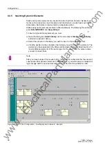
In order to draw and parameterize the substation you must:
Start the
DIGSI Plant Configuration
Insert
Typicals
anywhere you need them in the chart (Chapter 4.3.9, page 62).
Draw the required
busbars
and name them (Chapter 4.3.3, page 52).
Insert
bay names
to define the required bays (Chapter 4.3.4, page 54).
Insert
dynamic elements
of the libraries into the substation chart (Chapter 4.3.5,
Link
the dynamic elements with the busbars. Use lines and connections for this pur-
pose (Chapter 4.3.6, page 58).
Insert
static text
e.g., for comments (Chapter 4.3.8, page 61).
Create
Typicals
for frequently used substation components and insert them into
the chart where needed (Chapter 4.3.9, page 62).
Save
the substation chart and
exit
the DIGSI Plant Configuration (Chapter 4.3.10,
We will illustrate the configuration by the example of a double busbar with bus coupler.
Note
Standard bays such as bus couplers and feeder bays are already available as
Typi-
cals
. You can find Typicals and Templates in the folder
SSTypicals
. The DIGSI Plant
Configuration interprets the data correctly.
www
. com


