1.1 Overall Operation
17
7ST6 Manual
E50417-G1176-C251-A3
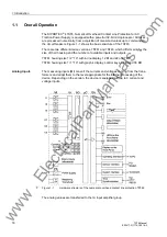
The IA input amplifier group allows high impedance connection for analog input values
and contains filters optimized with regard to bandwidth and processing speed for mea-
sured value processing.
In the analog/digital converter unit, the analog input values are sampled, digitized and
supplied to the microcomputer system.
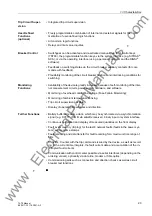
Microcomputer
System
Apart from processing the measured values, the microcomputer system
µ
C also exe-
cutes the actual protection and control functions. They especially consist of:
• Filtering and conditioning of the measured values
• Continuous monitoring of the measured values
• Monitoring of the pickup conditions for the individual protective functions
• Scanning of limit values and time sequences
• Control of signals for logic functions
• Deciding on trip and close commands
• Storage of indications, fault data and fault values for fault analysis purposes
• Management of the operating system and its functions, e.g. data memory, real-time
clock, communication, interfaces, etc.
The information is provided via output amplifier OA.
Binary Inputs and
Outputs
Binary inputs and outputs from and to the computer system are routed via the I/O
modules (inputs and outputs). The computer system obtains the information from the
system (e.g remote resetting) or the external equipment (e.g. blocking commands).
Additional outputs are mainly commands that are issued to the switching devices and
indications for remote signalling of events and states.
Front Elements
Optical indicators (LEDs) and a front LC display provide information on the function of
the device and indicate events, states and measured values.
Integrated control and numeric keys in conjunction with the LCD facilitate local inter-
action with the local device. All information of the device can be accessed using the
integrated control and numeric keys. The information includes protective and control
settings, operating and fault indications, measured values and settings (see also
Chapter 2 and SIPROTEC
®
4 System Description, Order No. E50417-H1176-C151).
Devices with control functions also allow station control on the front panel.
Serial Interfaces
Via the serial interface in the front panel the communication with a personal computer
using the operating program DIGSI
®
is possible. This ensures convenient operation of
all device functions.
The service interface can also be used for communication with a personal computer
using DIGSI
®
. This interface is particularly well suited in case of hard wiring between
the devices and the PC or in case of an operation via modem.
All device data can be transmitted to a central evaluating unit or control center through
the serial system (SCADA) interface. This interface may be provided with various
physical transmission modes and different protocols to suit the particular application.
An additional interface is designed for time synchronization of the internal clock by
means of external synchronization sources.
Further communication protocols can be implemented via additional interface mod-
ules.
www
. ElectricalPartManuals
. com

