background image

3 Mounting and Commissioning

226

7ST6 Manual

E50417-G1176-C251-A3
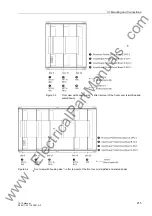
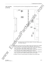
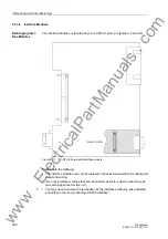
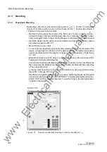
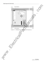
Input/Output Board 
B-I/O-2       

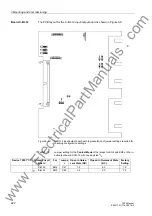
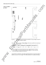
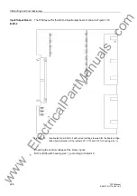
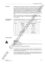
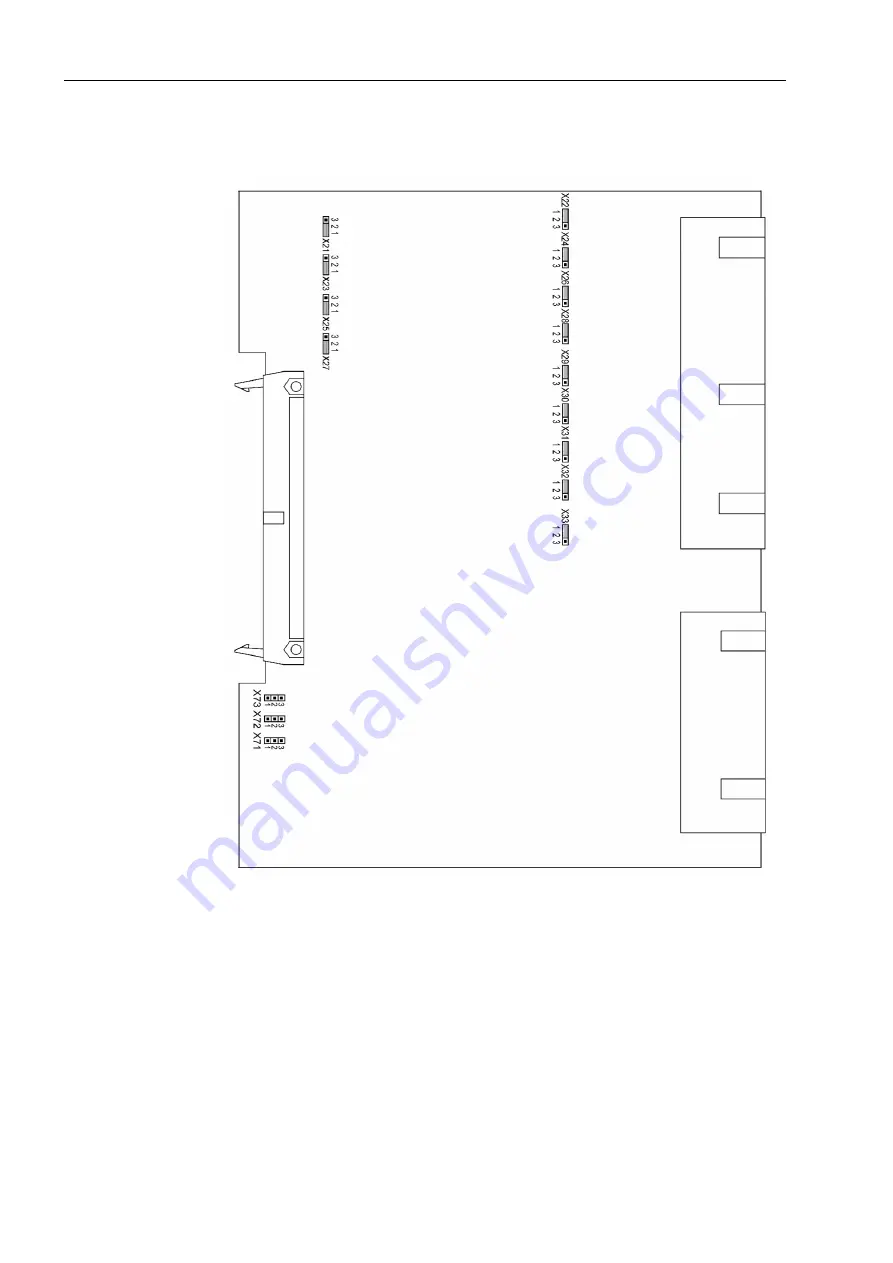
The PCB layout for the B-I/O-2 input/output board is shown in Figure 3-10.

Figure 3-10

Input/output board B-I/O-2 with jumper settings required for the board configu-
ration (representation of the jumpers X71, X72 and X73 for housing size 

1

/

1

)

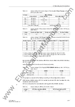
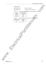
Checking the control voltages of the binary inputs:

BI13 to BI38 (with housing size 

1

/

1

) according to Table3-19.

www 

. ElectricalPartManuals 

. com

Summary of Contents for SIPROTEC 7ST6

Page 1: ...tection for AC Traction Power Supply 7ST6 V4 2 Manual E50417 G1176 C251 A3 Preface Introduction 1 Functions 2 Mounting and Commissioning 3 Technical Data 4 Appendix A Literature Glossary Index w w w E l e c t r i c a l P a r t M a n u a l s c o m ...

Page 2: ...right to make technical improvements without notice Copyright Copyright Siemens AG 2006 All rights reserved Dissemination or reproduction of this document or evaluation and communication of its contents is not authorized except where expressly permitted Violations are liable for damages All rights reserved particularly for the purposes of patent application or trademark registration Registered Tra...

Page 3: ... Firmware version V4 2 Indication of Con formity Additional Support Should you have any further questions regarding the SIPROTEC 4 system please contact your local Siemens distributor Additional informa tion Internet In order to remain up to date in the future please make use of the offer on our down load platform on the Internet under address http www siprotec de This product complies with the di...

Page 4: ...installation and safety regulations for work in power current plants e g ANSI IEC EN DIN or other national and international regulations must be observed Instructions and Warnings The warnings and notes contained in this manual serve for your own safety and for an appropriate lifetime of the device Please observe them The following indicators and standard definitions are used DANGER indicates that...

Page 5: ...f configuration or function parameters which may appear word for word in the display of the device or on the screen of a personal computer with DIGSI are marked in bold letters of a monospace font The same goes for the titles of menus 1234A Parameter addresses have the same character style as parameter names Param eter addresses in overview tables contain the suffix A if the parameter is only avai...

Page 6: ...ut is active if only one of the inputs is active Coincidence gate equivalence output is active if both inputs are active or inactive at the same time Dynamic inputs edge triggered above with positive below with negative edge Formation of one analog output signal from a number of analog input signals Limit stage with setting address and parameter designator name Timer pickup delay T example adjusta...

Page 7: ...tting Notes 30 2 1 2 4 Settings 31 2 1 2 5 Information List 31 2 1 3 Power System Data 1 33 2 1 3 1 Setting Notes 33 2 1 3 2 Settings 36 2 1 3 3 Information List 37 2 1 4 Change Group 38 2 1 4 1 Purpose of the Setting Groups 38 2 1 4 2 Setting Notes 38 2 1 4 3 Settings 39 2 1 4 4 Information List 39 2 1 5 Power System Data 2 40 2 1 5 1 Setting Notes 40 2 1 5 2 Settings 41 2 1 5 3 Information List ...

Page 8: ...tional Description 76 2 3 2 Setting Notes 79 2 3 3 Settings 82 2 3 4 Information List 83 2 4 High Speed Overcurrent Protection 84 2 4 1 Functional Description 84 2 4 2 Setting Notes 85 2 4 3 Settings 86 2 4 4 Information List 86 2 5 Emergency Overcurrent Protection 87 2 5 1 General 87 2 5 2 Functional Description 87 2 5 3 Setting Notes 88 2 5 4 Settings 89 2 5 5 Information List 89 2 6 Overvoltage...

Page 9: ...es 122 2 11 3 Settings 123 2 11 4 Information List 123 2 12 Automatic Reclosure Function 124 2 12 1 Functional Description 124 2 12 2 Setting Notes 131 2 12 3 Settings 139 2 12 4 Information List 140 2 13 Synchronism and Voltage Check 142 2 13 1 Functional Description 142 2 13 2 Setting Notes 145 2 13 3 Settings 150 2 13 4 Information List 151 2 14 Fault Locator 152 2 14 1 Functional Description 1...

Page 10: ... Hz 182 2 18 1 6 Setting Notes 183 2 18 2 Testing 184 2 18 2 1 Functional Description 184 2 18 2 2 Setting Notes 185 2 18 2 3 Information List 185 2 19 Auxiliary Functions 186 2 19 1 Message Processing 186 2 19 1 1 Functional Description 186 2 19 2 Measurement 190 2 19 2 1 Functional Description 190 2 19 2 2 Information List 191 2 19 3 Statistics 192 2 19 3 1 Functional Description 192 2 19 3 2 Se...

Page 11: ...a Connections of Serial Interfaces 236 3 2 2 Checking System Connections 238 3 3 Commissioning 240 3 3 1 Test Mode and Transmission Block 241 3 3 2 Checking Time Synchronization 241 3 3 3 Testing System Interfaces 242 3 3 4 Checking the Binary Inputs and Outputs 244 3 3 5 Tests for Circuit Breaker Failure Protection 247 3 3 6 Current and Voltage Test 248 3 3 7 Direction Check with Load Current 249...

Page 12: ...275 4 6 Circuit Breaker Failure Protection optional 276 4 7 Defrosting Protection depending on device version 277 4 8 Inrush Restraint optional 277 4 9 Automatic Reclosure Function optional 278 4 10 Synchronism and Voltage Check optional and depending on device version 279 4 11 Fault Locator optional 280 4 12 It Function optional 280 4 13 Trip Supervision 280 4 14 Trip Circuit Supervision 280 4 15...

Page 13: ... 299 A 4 1 Overcurrent Factors 299 Operational and Nominal Overcurrent Factor 299 Calculation Example according to IEC 60044 1 299 A 5 Default Settings 300 A 5 1 LEDs 300 A 5 2 Binary Input 301 A 5 3 Binary Output 302 A 5 4 Function Keys 303 A 5 5 Default Display 304 A 5 6 Pre defined CFC Charts 306 A 6 Protocol dependent Functions 309 A 7 Functional Scope 310 A 8 Settings 311 A 9 Information List...

Page 14: ...Contents 14 7ST6 Manual E50417 G1176 C251 A3 w w w E l e c t r i c a l P a r t M a n u a l s c o m ...

Page 15: ...ST6 device is introduced in this chapter An overview of the scope of application the properties and functional scope of the device is provided 1 1 Overall Operation 16 1 2 Application Scope 19 1 3 Characteristics 21 w w w E l e c t r i c a l P a r t M a n u a l s c o m ...

Page 16: ...ousing and the number of available inputs and outputs 7ST61 housing size 1 2 19 with 4 line display 12 BI and 22 or 27 BO 7ST63 housing size 1 1 19 with graphic display control keys 38 BI and 36 BO Analog Inputs The measuring inputs MI convert the currents and voltages coming from the trans formers and adapt them to the level appropriate for the internal processing of the device Depending on the v...

Page 17: ...ns for remote signalling of events and states Front Elements Optical indicators LEDs and a front LC display provide information on the function of the device and indicate events states and measured values Integrated control and numeric keys in conjunction with the LCD facilitate local inter action with the local device All information of the device can be accessed using the integrated control and ...

Page 18: ...y a power supply PS with the neces sary power in the different voltage levels Brief supply voltage dips which may occur on short circuits in the auxiliary voltage supply of the power system are usually bridged by a capacitor see also Technical Data Chapter 4 w w w E l e c t r i c a l P a r t M a n u a l s c o m ...

Page 19: ... as an option Beside the short circuit protection functions described above the device offers addi tional protection functions such as multiple stage overvoltage and undervoltage pro tection circuit breaker failure protection and thermal overload protection which pro tects the overhead contact line from excessive heating due to overloads The fault locator supports fast location of the fault after ...

Page 20: ...d to a number of LEDs on the front cover allocat able can be externally processed via output contacts allocatable linked with user definable logic functions and or issued via serial interfaces During a fault system fault important events and changes in conditions are saved in fault logs Event Log or Trip Log Instantaneous fault values are also saved in the device and may be analysed subsequently C...

Page 21: ... non directional forward ex tended reverse Combined tripping characteristic with separate setting of reach absolute imped ance value Z angle and load limitation resistance R Adaptation to different switching states of the overhead contact line during opera tion is ensured by the changeover function of the impedance stages Instantaneous tripping when switching onto a fault Inrush restraint possible...

Page 22: ...Automatic Reclosure Function optional Single or multiple reclosure up to 8 reclosure attempts With separate idle and operating times for the first 4 reclosure attempts Synchronism check before reclosing Synchronism and Voltage Check optional Verification of the synchronous conditions before energisation Fast measuring of voltage difference UDiff of the phase angle difference ϕ Diff and frequency d...

Page 23: ...software Monitoring of overhead contact line voltage Fuse Failure Monitoring Monitoring of ambient temperature sensing Trip circuit supervision possible Display of operating impedances and direction Further Functions Battery buffered real time clock which may be synchronized via a synchronization signal e g DCF77 IRIG B via satellite receiver binary input or system interface Continuous calculation...

Page 24: ...1 Introduction 24 7ST6 Manual E50417 G1176 C251 A3 w w w E l e c t r i c a l P a r t M a n u a l s c o m ...

Page 25: ...Speed Overcurrent Protection 84 2 5 Emergency Overcurrent Protection 87 2 6 Overvoltage and Undervoltage Protection 90 2 7 Thermal Overload Protection 94 2 8 Circuit Breaker Failure Protection 103 2 9 Trip Supervision 109 2 10 Defrosting Protection 111 2 11 InRush Restraint 120 2 12 Automatic Reclosure Function 124 2 13 Synchronism and Voltage Check 142 2 14 Fault Locator 152 2 15 It Function curr...

Page 26: ... 7ST6 relay contains a series of protective and additional functions The hardware and firmware provided is designed for this scope of functions In addition the command functions can be matched to the system conditions Individual functions can be activated or deactivated during the configuration procedure The interaction of functions may also be modified The available protective and additional func...

Page 27: ...o four different groups of settings may be changed quickly and easily during device operation see also Subsection 2 1 4 Only one setting group may be selected and used if the setting is Disabled The impedance characteristic valid for distance protection is selected under address 113 DISTANCE CURVE You can choose between distance protection with combined tripping characteristic and distance protect...

Page 28: ...y Overcurrent Protection X Thermal Overload Protection X Ambient Temperature Sensing X Trip Circuit Supervision X Defrosting Protection X Current time Integral X High Speed Overcurrent Protection X Inrush Restraint X Automatic Reclosure X Synchro check X Circuit Breaker Failure Protection X Voltage Protection X Fault Locator X w w w E l e c t r i c a l P a r t M a n u a l s c o m ...

Page 29: ...rcurrent Protec tion 133 Auto Reclose Disabled Enabled Enabled Auto Reclose Function 135 Synchro Check Disabled Enabled Enabled Synchronism and Voltage Check 137 O U VOLTAGE Disabled Enabled Enabled Under Overvoltage Protection 138 Fault Locator Disabled Enabled Enabled Fault Locator 139 BREAKER FAILURE Disabled Enabled Enabled Breaker Failure Protection 140 Trip Cir Sup Disabled Enabled Disabled ...

Page 30: ...2 Spontaneous Indications on the Display You can determine whether or not the most important data of a fault event is displayed automatically after the fault has occurred see also Fault indications in Section 2 19 1 Auxiliary Functions 2 1 2 3 Setting Notes Fault Indications Pickup of a new protective function generally turns off any previously lit LEDs so that only the latest fault is displayed a...

Page 31: ...or FMS2 OUT Error FMS FO 2 Brk OPENED IntSP Breaker OPENED FdrEARTHED IntSP Feeder EARTHED 1 Not configured SP No Function configured 2 Non Existent SP Function Not Available 3 Time Synch SP Synchronize Internal Real Time Clock 5 Reset LED SP Reset LED 15 Test mode SP Test mode 16 DataStop SP Stop data transmission 51 Device OK OUT Device is Operational and Protecting 55 Reset Device OUT Reset Dev...

Page 32: ...rror Board 1 OUT Error Board 1 184 Error Board 2 OUT Error Board 2 185 Error Board 3 OUT Error Board 3 186 Error Board 4 OUT Error Board 4 187 Error Board 5 OUT Error Board 5 188 Error Board 6 OUT Error Board 6 189 Error Board 7 OUT Error Board 7 190 Error Board 0 OUT Error Board 0 192 Error1A 5Awrong OUT Error 1A 5Ajumper different from setting 193 Alarm adjustm OUT Alarm Analog input adjustment ...

Page 33: ...n the Appendix under A 3 At address 202 CT PRIMARY you set the primary rated CT current overhead contact line current The secondary rated current is set in address 203 CT SECONDARY At addresses 204 Unom PRIMARY and 205 Unom SECONDARY information is entered regarding the primary and secondary current ratings of the current transformers It is important to ensure that the rated secondary current of t...

Page 34: ...e the synchro check function Enabled ad dress 135 has been configured the following parameters must be set in the P System Data 1 At address 215 Uline Uref you set the matching factor for the different transform ers of the overhead contact line Vline and of the reference voltage Vref System Data The permissible rated frequencies depend on the device variant 16 7 Hz or 25 to 60 Hz In the second var...

Page 35: ...tion TMax CLOSE CMD is set This applies to all close commands issued by the device It also determines the length of the close command pulse when a circuit breaker test cycle is issued via the device It must be chosen to ensure that the circuit breaker can always close reliably There is no risk in setting this time too long as the close command will in any event be termi nated following a new trip ...

Page 36: ...ards Busbar towards Line IF CT Starpoint 207 IF CT PRIMARY 10 5000 A 1000 A CT Rated Primary Current IF 209 UF PRIMARY 1 0 150 0 kV 15 0 kV Rated Primary Voltage UF 210 UF SECONDARY 50 0 130 0 V 100 0 V Rated Secondary Voltage UF 211 IX CT STARPOINT towards Line towards Busbar towards Line IX CT Starpoint 212 IX CT PRIMARY 10 5000 A 1000 A CT Rated Primary Current IX 213 CURRENT I1 I2 Separate I1 ...

Page 37: ...st 245 BI CONTROL Edge Level Edge Control of BI for Changeover Functions 251 BkrClosed I MIN 1A 0 04 1 00 A 0 04 A Closed Breaker Min Current Threshold 5A 0 20 5 00 A 0 20 A 260 Ir CB 10 50000 A 1250 A Rated Normal Current Circuit Breaker 261 OP CYCLES AT Ir 100 1000000 10000 Switching Cycles at Rated Normal Current 262 Isc CB 10 100000 A 25000 A Rated Short Circuit Break ing Current CB 263 OP CYC...

Page 38: ...ser to save the corresponding settings for each applica tion When they are needed settings may be loaded quickly All setting groups are stored in the relay Only one setting group may be active at a given time 2 1 4 2 Setting Notes General If multiple setting groups are not required Group A is the default selection Then the rest of this section is not applicable If multiple setting groups are desir...

Page 39: ...Group B Group C Group D Binary Input Protocol Group A Change to Another Setting Group No Information Type of In formation Comments Group A IntSP Group A Group B IntSP Group B Group C IntSP Group C Group D IntSP Group D 7 Set Group Bit0 SP Setting Group Select Bit 0 8 Set Group Bit1 SP Setting Group Select Bit 1 w w w E l e c t r i c a l P a r t M a n u a l s c o m ...

Page 40: ... secondary reactance per unit length characteristic for the 1st line section in Ω km if the unit length set under System Data is km address 236 see Subsection 2 1 3 1 At address 1111 d1 you set the corresponding line length of the 1st line section The device needs these values for conversion of the fault impedance into a fault distance At address 1160 X1 you set the secondary reactance per unit le...

Page 41: ...17 d4 1 00 200 00 km 0 20 00 km Line Length 4th Section 1118 X5 1A 0 05 50 00 Ω km 0 20 Ω km Reactance per Unit Length 5th Section 5A 0 01 10 00 Ω km 0 04 Ω km 1119 d5 1 00 200 00 km 0 20 00 km Line Length 5th Section 1130 X1 REV 1A 0 05 50 00 Ω km 0 20 Ω km Reactance Unit Length 1th Section Rev 5A 0 01 10 00 Ω km 0 04 Ω km 1131 d1 REV 1 00 200 00 km 0 20 00 km Line Length 1th Section Reverse 1132...

Page 42: ... Unit Length 5th Section 5A 0 01 16 00 Ω mi 0 06 Ω mi 1169 d5 0 60 124 00 Miles 0 12 50 Miles Line Length 5th Section 1180 X1 REV 1A 0 05 80 00 Ω mi 0 30 Ω mi Reactance Unit Length 1th Section Rev 5A 0 01 16 00 Ω mi 0 06 Ω mi 1181 d1 REV 0 60 124 00 Miles 0 12 50 Miles Line Length 1th Section Reverse 1182 X2 REV 1A 0 05 80 00 Ω mi 0 30 Ω mi Reactance Unit Length 2th Section Rev 5A 0 01 16 00 Ω mi ...

Page 43: ...y GENERAL TRIP command 530 LOCKOUT IntSP LOCKOUT is active 536 Final Trip OUT Final Trip 545 PU Time VI Time from Pickup to drop out 546 TRIP Time VI Time from Pickup to TRIP 561 Man Clos Detect OUT Manual close signal detected 562 Man Close Cmd OUT CB close command for manual closing 563 CB Alarm Supp OUT CB alarm suppressed 1191 Pckup TstUnit OUT Pickup autom testunit overh cont line 2730 CB Rea...

Page 44: ...ng intervals of the available rated frequencies For a fault the data are stored for an adjustable period of time but no more than 5 seconds per fault A total of 8 records can be saved within 15 s The fault record memory is automatically updated with every new fault so no acknowledgment for pre viously recorded faults is required The storage of fault values can be started by pickup of a protection ...

Page 45: ...r the dropout of the recording criterion Usually this is also the extent of a fault recording address 403 WAVEFORM DATA Fault event If automatic reclosure is implemented the entire system disturbance possibly with several reclose attempts up to the ultimate fault clearance can be stored address 403 WAVEFORM DATA Pow Sys Flt This facilitates the representation of the entire system fault history but...

Page 46: ...M DATA Fault event Pow Sys Flt Fault event Scope of Waveform Data 410 MAX LENGTH 0 30 5 00 sec 1 00 sec Max length of a Waveform Capture Record 411 PRE TRIG TIME 0 05 0 50 sec 0 10 sec Captured Waveform Prior to Trigger 412 POST REC TIME 0 05 0 50 sec 0 10 sec Captured Waveform after Event 415 BinIn CAPT TIME 0 10 5 00 sec 0 50 sec Capture Time via Binary Input No Information Type of In formation ...

Page 47: ... protection can be switched on or off by parameter settings or via a binary input Switching the function on or off via the binary inputs Dis prot on FNo 3601 and Dis prot off FNo 3602 is done with edge triggering The distance protection can also be dynamically blocked via the binary input BLOCK Distance FNo 3603 The distance protection is equipped with an overcurrent pickup function For precise im...

Page 48: ...impedance This allows a better distinction between fault and load range and an improved behav iour of the protection function is the presence of arc faults and close up faults with transformer saturation For each single curve the direction characteristic can be selected independently options are Forward Forward extended Reverse and Non directional The setting Forward extended has the same curve as...

Page 49: ...2 2 Distance Protection 49 7ST6 Manual E50417 G1176 C251 A3 Figure 2 3 Tripping characteristic of the combined characteristic w w w E l e c t r i c a l P a r t M a n u a l s c o m ...

Page 50: ...and load range and a better behaviour of the protection function is the presence of arc faults and close up faults with trans former saturation For each single curve the direction characteristic can be selected independently options are Forward Reverse and Non directional An extra characteristic Forward extended is available for the detection of close up faults This characteristic differs from the...

Page 51: ...2 2 Distance Protection 51 7ST6 Manual E50417 G1176 C251 A3 Figure 2 4 Tripping characteristic of the polygonal characteristic w w w E l e c t r i c a l P a r t M a n u a l s c o m ...

Page 52: ...e of a short circuit For the definition of these threshold values the load variations which are a function of the distance between the feeding point and the vehicle must be taken into account You can set parameter Rel T2K at address 1210 for zone 2 and Rel T3K at address 1220 for zone 3 to determine whether the criteria di dt and du dt are to be combined via AND or via OR Refer to Figure 2 6 You c...

Page 53: ...2 2 Distance Protection 53 7ST6 Manual E50417 G1176 C251 A3 Figure 2 6 Logic of the short circuit detection w w w E l e c t r i c a l P a r t M a n u a l s c o m ...

Page 54: ... cycle of the AR function The zones Z2 and Z3 have each two different tripping times The indications Dis T2K active FNo 3909 and Dis T3K active FNo 13804 are used to control which of the two tripping times is effective for each stage These signals are provided by the short circuit detection function In zones Z2 and Z3 only one of the two tripping times can be active at a time In zone Z2 the short ...

Page 55: ...E50417 G1176 C251 A3 Figure 2 7 Tripping logic of independent zones The logic for providing the direction signals and the general pickup and trip are shown separately in the figure below w w w E l e c t r i c a l P a r t M a n u a l s c o m ...

Page 56: ...2 Functions 56 7ST6 Manual E50417 G1176 C251 A3 Figure 2 8 Overreach logic of the distance protection w w w E l e c t r i c a l P a r t M a n u a l s c o m ...

Page 57: ...al protection device The control signals for this arrive at the binary inputs AR Start and Trip for AR Figure 2 9 Tripping logic of dependent zones In the initial state with the Distance prot switched on and the Auto Reclose operative zone Z1B is enabled With the function Auto Reclose switched off or not operative zone Z1 is enabled Before the 2nd reclosure cycle the enable for zone Z1B is reset a...

Page 58: ...nual Close Signal To make undelayed tripping possible on switching of a faulted line the control discrep ancy switch can use a binary input to issue the manual close command to the over head contact line protection system To do so the external signal Manual Close must be configured to a binary input The figure below shows the logic diagram for this Figure 2 10 Tripping logic of the manual close zo...

Page 59: ... parameter 1205 CHANGE ZONE setting options are Binary Input Protocol Setting or Blocked The control sources Binary Input and Protocol can continue to be operated even if they are not activated However the status Zx or Zx Stroke set in this way will not take effect until the associated control source is selected again see Figure 2 11 For zone changeover by Protocol the commands 13811 through 13813...

Page 60: ...oad range in this section general desig nations will be used Table 2 2 shows the assignment of these designations to the con crete parameters of a zone On long highly loadable lines there is a risk of the load impedance rising as high as the tripping area of the distance protection In order to avoid spurious pickup of the dis tance protection during the transfer of high powers the load range can b...

Page 61: ...terconnected system This diagram should reflect the line lengths with their primary reactances X in Ω km For the reach of the distance zones the reactance X is the deciding quantity The first zone Z1 is usually set to cover 85 of the protected line without any trip time delay i e T1 0 00 s The protection clears faults in this range without additional time delay i e the tripping time is the relay b...

Page 62: ...ending on the quality of the measured values different computation techniques are used Immedi ately after fault inception the short circuit voltage is disturbed by transients The voltage memorized prior to fault inception is therefore used in this situation If there is neither a current measured voltage nor a memorised voltage available which is suffi cient for measuring the direction the forward ...

Page 63: ...ion of the characteristic parameters in this section general designa tions will be used Table 2 2 shows the assignment of these designations to the actual parameters of a zone The reach of the characteristic is set with the parameter Z Here you set the absolute value of the balance point impedance without taking into account an arc resistance for the zone For more information on setting the reach ...

Page 64: ...et with the parameter X Here you set the balance point reactance for the zone For more information on setting the reach please refer to margin heading Grading Coordination Chart The load range is set with the parameters for the minimum load impedance RL and the spread angle of the load range Alpha α For more information on setting the load range parameters please refer to margin heading Load Range...

Page 65: ... polygonal and the same angle parameters α β γ as zone Z1 Therefore these parameters cannot be set for the AR zones They are nor DIGSI set ting sheet Parameter Setting parameters Z active Z Strk active Zone Z1 Z X RL Z1 Addr 1310 X1 Addr 1309 R1 Addr 1308 Z1 Reverse Addr 1316 X1 Reverse Addr 1315 R1 Reverse Addr 1314 Z1 Strk Addr 1318 X1 Strk Addr 1317 R1 Strk Addr 1207 Z1 Strk Reverse Addr 1320 X...

Page 66: ...l closure This setting of the parameter SI Time Man Cl address1150 is only possible with DIGSI under Additional Settings see Subsection 2 1 5 1 This zone is provided for protection of the entire line by instanta neous tripping It has therefore the same settings as zone Z1B The following parameters can be set for the dependent zones Table 2 3 Assignment of setting parameters for the dependent zones...

Page 67: ...lies on the fact that in case of an overload the difference between the phasors of the currently measured current and of the current measured two cycles ago is much less than in case of a short circuit This current difference is defined by the parameters di dt Z2 address 1343 and di dt Z3 address 1363 referred to the rated current The change of the value of the current and the voltage are also tak...

Page 68: ... results Setting value secondary USec 15kV 0 1kV 9 5kV 63 3V By setting the du dt or di dt parameters to 0 the grading margin T2K or T3K is re leased at the same time the timers T2L and T3L are blocked This blocking is sig nalled by the indication Dis T2K active or Dis T3K active By setting the du dt or di dt parameters to infinite the corresponding parts of the short circuit detection are disable...

Page 69: ...t di dt Z2 0 0 0 5 0 0 Restraint Factor of di dt Stage Z2 1217 R2 Strk 1A 0 20 250 00 Ω 10 00 Ω Resistance R Zone Z2 Reverse 5A 0 04 50 00 Ω 2 00 Ω 1218 R2 Strk Reverse 1A 0 20 250 00 Ω 10 00 Ω Resistance R Zone Z2 Stroke Reverse 5A 0 04 50 00 Ω 2 00 Ω 1220 Rel T3K di OR du di AND du di OR du Release of TK of Zone Z2 1221 Rest di dt Z3 0 0 0 5 0 0 Restraint Factor of di dt Stage Z3 1227 R3 Strk 1A...

Page 70: ...one Z1 Reverse 5A 0 04 50 00 Ω 2 00 Ω 1317 X1 Strk 1A 0 20 250 00 Ω 10 00 Ω Reactance X Zone Z1 Stroke 5A 0 04 50 00 Ω 2 00 Ω 1318 Z1 Strk 1A 0 20 250 00 Ω 10 00 Ω Impedance Z Zone Z1 Stroke 5A 0 04 50 00 Ω 2 00 Ω 1319 X1 Strk Reverse 1A 0 20 250 00 Ω 10 00 Ω Reactance X Zone Z1 Stroke Reverse 5A 0 04 50 00 Ω 2 00 Ω 1320 Z1 Strk Reverse 1A 0 20 250 00 Ω 10 00 Ω Impedance Z Zone Z1 Stroke Reverse 5...

Page 71: ... 250 00 Ω 9 00 Ω Resistance R Zone Z1L Reverse 5A 0 04 50 00 Ω 1 80 Ω 1337 X1L Reverse 1A 0 20 250 00 Ω 18 00 Ω Reactance X Zone Z1L Reverse 5A 0 04 50 00 Ω 3 60 Ω 1338 Z1L Reverse 1A 0 20 250 00 Ω 18 00 Ω Impedance Z Zone Z1L Reverse 5A 0 04 50 00 Ω 3 60 Ω 1341 Op Mode Z2 Forward Forward ext Reverse Non Directional Inactive Forward Operating Mode Distance Zone Z2 1342 Zone Sel Z2 Z active Z Strk ...

Page 72: ...0 Ω Impedance Z Zone Z2 Stroke 5A 0 04 50 00 Ω 4 00 Ω 1359 X2 Strk Reverse 1A 0 20 250 00 Ω 20 00 Ω Reactance X Zone Z2 Stroke Reverse 5A 0 04 50 00 Ω 4 00 Ω 1360 Z2 Strk Reverse 1A 0 20 250 00 Ω 20 00 Ω Impedance Z Zone Z2 Stroke Reverse 5A 0 04 50 00 Ω 4 00 Ω 1361 Op Mode Z3 Forward Forward ext Reverse Non Directional Inactive Forward Operating Mode Distance Zone Z3 1362 Zone Sel Z3 Z active Z S...

Page 73: ...378 Z3 Strk 1A 0 20 250 00 Ω 30 00 Ω Impedance Z Zone Z3 Stroke 5A 0 04 50 00 Ω 6 00 Ω 1379 X3 Strk Reverse 1A 0 20 250 00 Ω 30 00 Ω Reactance X Zone Z3 Stroke Reverse 5A 0 04 50 00 Ω 6 00 Ω 1380 Z3 Strk Reverse 1A 0 20 250 00 Ω 30 00 Ω Impedance Z Zone Z3 Stroke Reverse 5A 0 04 50 00 Ω 6 00 Ω 1381 Op Mode ZOR Forward Forward ext Reverse Non Directional Inactive Forward Operating Mode Over reach Z...

Page 74: ...3758 Dis Pickup Z3 OUT Distance Pickup Z3 3771 Dis Time Out T1 OUT DistanceTime Out T1 3780 Dis TimeOut T1B OUT DistanceTime Out T1B 3783 Dist T1L OUT Dist Time T1L Zone Z1L expired 3801 Dis Gen Trip OUT Distance protection General trip 3810 Dis Trip Z1 OUT Dist Trip in Zone Z1 3900 DisZ1str act SP Dist Zone Z1 stroke is active 3901 Dis Z1 act SP Dist Zone Z1 is active 3902 DisZ2str act SP Dist Zo...

Page 75: ...ce Zone Z2Stroke ON 13813 Z3StrkON OFFser IntSP Distance Zone Z3Stroke ON 13840 Dis Rush blk OUT Distance Protection Inrush blocked 13890 Dis PU Z1B OUT Distance Prot Picked up in Zone Z1B 13891 Dis PU Z1L OUT Distance Prot Picked up in Zone Z1L 13892 Dis PU Z2di dt OUT Picked up di dt function in Zone Z2 13893 Dis PU Z2du dt OUT Picked up du dt function in Zone Z2 13894 Dis PU Z3di dt OUT Picked ...

Page 76: ...nd are freely combinable Instan taneous tripping can be set in all stages when the protected line is switched onto a fault If some stages are not needed those not needed can be deactivated by setting the pickup value to The time overcurrent protection can be switched on or off by parameter settings or via binary inputs The figure below shows the control logic Figure 2 13 Control logic of the overc...

Page 77: ...t is common to all stages The parameter O C SOTF Trip address 2603 specifies whether instantaneous tripping of this stage via the binary input Manual Close FNo 356 is possible YES or not possible NO Furthermore all stages can be blocked by the inrush restraint function This blocking can be switched on YES or off NO in the parameter Inrush O C A blocking signal generates the indication O C Rush blk...

Page 78: ...OC ANSI or TOC IEC This parameter is also used to make a preselection of the characteristics available in the inverse time overcurrent stage This stage differs from the definite time overcurrent stage I by its current dependent delay time characteris tic The delay time of the stage is the delay time associated with the applied current in the selected characteristic Selectable characteristics are s...

Page 79: ... overcurrent protection The overcurrent stage I stage may operate either as a definite time overcurrent protection address 2602 CURVE O C Definite Time or as an time overcurrent protection with current dependent characteristic address 2602 CURVE O C TOC IEC If some stages are not needed those not needed can be deactivated by setting the pickup value to If you set one assigned time stage to the del...

Page 80: ... secondary values If secondary quantities are used all currents must be converted to the secondary side of the current transformers The time delay T I address 2615 results from the time grading schedule designed for the network If implemented as emergency overcurrent protection shorter tripping times are advisable one grading time step above the fast tripping stage as this func tion is only activa...

Page 81: ... the following characteristics are available in address 2612 ANSI Curve Inverse Short Inverse Long Inverse Moderately Inv Very Inverse Extremely Inv and Definite Inv For the setting of the pickup value IP address 2617 the following must be observed Pickup only occurs at a current which is approximately 10 above the set value The dropout threshold is the setting value The time multiplier D IP addre...

Page 82: ... HighSetStage 5A 0 50 125 00 A 20 00 A 2606 T I 0 00 30 00 sec 0 10 sec Delay Time T I Very High Set Stage 2608 I 1A 0 10 25 00 A 2 00 A I Pickup 5A 0 50 125 00 A 10 00 A 2609 T I 0 00 30 00 sec 0 30 sec T I Time Delay 2611 IEC Curve Normal Inverse Very Inverse Extremely Inv LongTimeInverse Normal Inverse IEC Curve 2612 ANSI Curve Inverse Short Inverse Long Inverse Moderately Inv Very Inverse Extr...

Page 83: ...92 O C PICKUP I OUT Overcurrent Pickup I 7201 I STUB PICKUP OUT O C I STUB Pickup 7211 O C TRIP OUT Overcurrent General TRIP command 7221 O C TRIP I OUT Overcurrent TRIP I 7222 O C TRIP I OUT Overcurrent TRIP I 7235 I STUB TRIP OUT O C I STUB TRIP 13820 O C ON SP Switch on Overcurrent Protection 13821 O C OFF SP Switch off Overcurrent Protection 13822 O C ON OFF BI IntSP Overcurrent Protection ON ...

Page 84: ...set tings or via binary inputs The figure below shows the control logic Figure 2 16 Control logic of the instantaneous high speed overcurrent protection function The instantaneous value of the overhead contact line current or the sum of the over head contact line current and the current of the negative feeder 2 1 3 1 is compared with the setting I HS O C address 2404 When the settable delay time T...

Page 85: ...n On deliv ery this jumper setting is for without summation The threshold I HS O C address 2404 is set as an RMS value The setting value is converted internally to the peak current value and used for threshold comparison Depending on the phase angle of the voltage on fault inception the short circuit current can be superimposed by a decaying DC component The peak value of the short circuit current...

Page 86: ... 5 125 A 50 A 2405 T HS O C 0 006 0 100 sec 0 0 000 sec High Speed O C Delay Time 2408 HS O C TRIP single channel dual channel dual channel HS O C TRIP Allocation No Information Type of In formation Comments 4271 HS O C OFF OUT HS O C is switched OFF 4281 HS O C PICKUP OUT HS O C PICKED UP 4293 HS O C TRIP OUT HS O C TRIPPED 13815 HS O C TRIP M OUT HS O C TRIPPED M 13816 HS O C ON SP Switch on HS ...

Page 87: ...or in Section 2 16 or Distance protection is switched off or ineffective Figure 2 18 Control logic of the emergency overcurrent protection 2 5 2 Functional Description Emergency Over current Protection The emergency overcurrent protection has a time overcurrent stage with current inde pendent trip time Undelayed tripping can be set when the protected line is switched onto a fault If the stage is n...

Page 88: ...rotection is not operative In address 2701 the time overcurrent protection can also be switched OFF In case of switching onto a fault the protection should trip instantaneously To do so set in address 2702 SOTF Emerg O C YES If the pickup threshold is exceeded when switching onto a fault the delay time set for the function is bypassed and the emergency overcurrent protection issues an instantaneou...

Page 89: ...minal current of the current transformer 2 5 5 Information List Addr Parameter C Setting Options Default Setting Comments 2303 Inrush O C BU NO YES NO Emerg O C Blocked by Inrush 2701 Emerg O C ON OFF ON Emergency Overcurrent Function 2702 SOTF Emerg O C NO YES NO Instantan trip after Switch onto Fault 2705 I Emerg O C 1A 0 10 25 00 A 2 00 A Emergency O C Pickup Current 5A 0 50 125 00 A 10 00 A 27...

Page 90: ...cur e g on long overhead contact lines under low load conditions especially in auto transformer systems with several auto transform ers along the line in islanded systems when generator voltage regulation fails or after full load shutdown of a generator and with the generator disconnected from the system The undervoltage protection can be applied for example for disconnection or load shedding task...

Page 91: ...e 2 21 Control and pick up tripping logic of the undervoltage protection With the parameter 3711 UNDERVOLTAGE the undervoltage protection can be switched ON or OFF The indication UNDER OFF is output when the function is switched on off The undervoltage protection is blocked when at least one of the signals Dis PICKUP or Failure Umeas is active The signal Failure Umeas prevents the undervoltage pro...

Page 92: ...s set e g 1 5 times the rated voltage 0 1 s to 0 2 s are sufficient for the time delay T U address 3704 Undervoltage The undervoltage stages can be switched ON or OFF in address 3711 UNDERVOLTAGE This undervoltage protection function has two stages The U stage address 3715 operates with the longer set time T U address 3716 for minor undervoltages It must not be set to more than the undervoltage pe...

Page 93: ...sec Delay Time Undervoltage U 3715 U 20 120 V 0 70 V Pickup Undervoltage U pos seq 3716 T U 0 00 60 00 sec 2 00 sec Delay Time Undervoltage U No Information Type of In formation Comments 4331 U Detection OUT Overvoltage detection Stage U 4332 U Detection OUT Overvoltage detection Stage U 4335 U Trip OUT Overvoltage trip Stage U 4336 U Trip OUT Overvoltage trip Stage U 13830 OVER OFF OUT Overvoltag...

Page 94: ... in accordance with a single body thermal model based on the following differential equation with TEMP Current overtemperature referred to the ambient temperature τ Thermal time constant of the contact line TRise Final overtemperature at current ITRise ITRise Current leading to the final temperature TRise CHANGE TO CAT Parameter for catenary changeover used for modi fying the characteristic where ...

Page 95: ...ly and its own housing A Pt100 temperature sensor is used for this purpose This device delivers at its output a load independent current 4 20 mA TD input which can be looped through up to 20 connected 7ST6 devices via an isolating amplifier The ambient temperature sensing feature is available for the temperature ranges between 30 C and 55 C and between 55 and 55 C A failure of the ambient temperat...

Page 96: ...ss 4215 AMB TEMP is used for the cal culation and the indication Fail TEMPSENS FNo 158 is output too Figure 2 24 Ambient temperature sensing The parameter MIN TEMP PRESET address 4216 is provided for line sections where the temperature is higher than at the location of the ambient temperature sensing e g tunnels in winter ambient temperature 15 C tunnel temperature 8 C In such a case a lower thres...

Page 97: ...t take effect until the associated control source is selected again see logic diagram 2 25 For a changeover via Protocol the commands 13827 to 13829 O C Cat1 2 3ON are provided With the setting Binary Input changeover between the catenaries CAT1 CAT2 and CAT3 is performed using the binary input indications Cat 1 active FNo 6605 Cat 2 active FNo 6604 and Cat 3 active FNo 6603 The binary inputs can ...

Page 98: ...s 98 7ST6 Manual E50417 G1176 C251 A3 The figure below shows the control logic of the catenary changeover Figure 2 25 Control logic of the catenary changeover w w w E l e c t r i c a l P a r t M a n u a l s c o m ...

Page 99: ...ry current 750 A Set valueTAU 3 3 min Permissible current for application time other than 1 s e g for 0 5 s Limit Current Factor k ITRise The limit current factor is set in address 4204 k ITRise It is determined by the re lation between the permissible thermal continuous current and this rated current The permissible continuous current is at the same time the current at which the e func tion of th...

Page 100: ...ovided that the thermal auto matic reclosure function is activated address 3450 AUTO TH AR ON see Section 2 12 Catenary Changeover In address 4202 CAT CHANGEOVER you select the control source for catenary changeover Catenary changeover is possible via binary input via protocol or via pa rameters If CAT CHANGEOVER Blocked is set CAT 1 is valid for 1 catenary Ambient Tempera ture Sensing If ambient ...

Page 101: ... C 15 C Ambient Temperature Value 4216 MIN TEMP PRESET 55 40 C 55 C Minimum Setting Ambient Tem perature No Information Type of In formation Comments 1501 O L on SP Switch on thermal overload protection 1502 O L off SP Switch off thermal overload protection 1511 Th Overload OFF OUT Thermal Overload Protection OFF 1516 O L Θ Alarm OUT Overload Alarm Near Thermal Trip 1521 ThOverload TRIP OUT Therma...

Page 102: ... Telegram 13980 Cat 1 ON OFF BI IntSP Catenary 1 ON OFF about Binary Input 13981 Cat 2 ON OFF BI IntSP Catenary 2 ON OFF about Binary Input 13982 Cat 3 ON OFF BI IntSP Catenary 3 ON OFF about Binary Input No Information Type of In formation Comments w w w E l e c t r i c a l P a r t M a n u a l s c o m ...

Page 103: ...run as long as a trip command is present and current continues to flow through the breaker poles Figure 2 26 Simplified function diagram of circuit breaker failure protection with current flow monitoring Normally the breaker will open and interrupt the fault current The current monitoring stage quickly resets typically 1 2 cycle of the power system frequency and stops the timers tBF1 address 3904 ...

Page 104: ...ilure protection is intended to be initiated by further external protection devices it is recommended for security reasons to connect two starting criteria to the device Therefore the trip command of the external protection should not be directly connected to the binary input BrkFail extSRC FNo 1431 For such an appli cation create a CFC chart combine in this chart the general device pickup and the...

Page 105: ...reaker failure protection the trip command of the overhead contact line protection is usually repeated after a first time stage to the feeder circuit breaker often via a second trip coil or set of trip coils if the breaker has not responded to the original trip command The signal 1471 BrkFailure TRIP is provided for this trip command repetition A second time stage monitors the response to this rep...

Page 106: ...nd are tripped after a delay time tBF2 address 3905 following initiation should the fault not have been cleared within this time The timer tBF1 address 3904 is set to in this case as it is not needed You can also use the first stage as the only one In that case you have to set the time tBF1 address 3904 Set tBF2 address 3905 to or equal to tBF1 address 3904 Be sure that the correct trip commands a...

Page 107: ...two stages can be set separately For trip repetition to the local feeder circuit breaker after a trip of the feeder protec tion tBF1 address 3904 For trip of the adjacent circuit breakers busbar zone tBF2 address 3905 The delay times are determined from the maximum operating time of the feeder circuit breaker the reset time of the current detectors of the breaker failure protection plus a safety m...

Page 108: ... tBF2 0 10 10 00 sec 0 75 sec Delay Time Higher Level Protection No Information Type of In formation Comments 157 Fail MAIN CB OUT Failure of main circuit breaker 1401 BF on SP BF Switch on breaker fail protection 1402 BF off SP BF Switch off breaker fail protection 1431 BrkFail extSRC SP Breaker failure initiated externally 1440 BkrFailON offBI IntSP Breaker failure prot ON OFF via BI 1451 BkrFai...

Page 109: ...mmand has been detected the indication CB Fault FNo 1491 is output This indication is reset before the set supervision has elapsed if the device detects that the current flow has been interrupted or if the signal Ext CB Trip FNo 1438 indicates that the external TRIP signal has been reset The interruption of the current flow is monitored by a current threshold When this threshold which is set with ...

Page 110: ...imum duration of the trip supervision is set with parameter T I CB MAX in address 2922 The supervision duration begins on activation of the signal Ext CB Trip FNo 1438 After the set supervision time T I CB MAX has elapsed a signal generated by the trip supervision CB Fault FNo 1491 is reset 2 9 3 Settings The table indicates region specific presettings Column C configuration indicates the correspo...

Page 111: ...rent protection is provided that monitors the defrosting current 2 10 1 Functional Description General Note During defrosting the overhead contact line is in a special switching state All other protection functions remain active when the defrosting protection is switched on The defrosting current can cause spurious tripping by one or more protection functions e g by the overvoltage protection or a...

Page 112: ...red with the other protection functions another current transformer is needed for the defrosting current flowing back This transformer is connected to the Ix input Note In auto transformer systems the negative feeder current IF is measured as well If the negative feeder has its own current transformer this current need not be consid ered as the current IF is very low in the special defrosting swit...

Page 113: ...ondition i t ix t 0 is not wholly fulfilled in fault free condition Therefore a value greater than zero must be used as tripping threshold With a high load current the differential current is higher than with a low load current Therefore a load dependent tripping threshold is required The restraint current is then calculated as follows The restraint current is a measure of the current load The pic...

Page 114: ...ristic is determined by the parameters k and Id The value for Id results from shunt currents which are independent of the defrosting cur rent and which can occur in fault free condition Such currents can be caused by ca pacitive leakage currents or by the magnetizing currents of power transformers located upstream of the protected zone The slope k to be set results from possible amplitude or angle...

Page 115: ...e basis of the differential protection characteristic is signalled as a pickup if the defrosting protection is switched on The pickup is signalled with the indication Defrost PICKUP and the TRIP command Defrost TRIP is output after the delay time T ID if the pickup condition is still present and the defrosting pro tection is not blocked The delay time allows to bridge transient compensation states...

Page 116: ...on of the defrosting protection Operational Mea sured Values In some models 3xI 3xU the defrosting current Ix is always displayed as an opera tional measured value It can be shown as a primary secondary or percent value If the defrosting protection is configured the differential current Id FNo 13968 calculated by the differential protection and the restraint current Ir FNo 13969 can be displayed a...

Page 117: ...3961 or via the system interface For control via the system interface the internal single point indication Defrost ON FNo 13963 is used Blocking There are various possibilities for blocking the defrosting protection If the protection is blocked only the TRIP indication Diff TRIP Fno 13975 will be blocked All other indications are output as before The defrosting protection can be blocked locally fr...

Page 118: ... have completely decayed after that time Typical values for these decay times are about 200 ms This time constant is reduced by resistances in the current path Backup Protection The backup protection of the defrosting protection function has two definite time over current stages The high current stage is set to approx 10 more than the transient current that is to be expected when switching on the ...

Page 119: ... IX 0 00 30 00 sec 0 50 sec Delay Time IX No Information Type of In formation Comments 13960 Defrost ON SP Switch on Defrosting Protection 13961 Defrost OFF SP Switch off Defrosting Protection 13962 BLOCK Defrost SP BLOCK Defrosting Protection 13963 Defrost ON IntSP Defrosting Protection is switched ON 13964 Defrost OFF OUT Defrosting Protection is switched OFF 13965 Defrost blk OUT Defrosting Pro...

Page 120: ...d transformer current depending on the switch on moment Although the fundamental current is evaluated by filtering of the measured current overfunctioning during energization of the transformer may result if very short delay times are set In the inrush current there is a substantial portion of fundamental current depending on the type and size of the transformer that is being energized The inrush ...

Page 121: ...s the harmonics content exceeds the value set in 2nd HARM BLOCK an inrush current is detected With the parameter Imax InrushRest a maximum current amplitude for using this criterion can be specified Above this current amplitude the detection of inrush cur rents on the basis of the second harmonics is blocked This blocking prevents that the inrush detection feature responds in case of transformer s...

Page 122: ...nrush blocking is effective The preset value 15 should be sufficient in most cases Lower values imply higher sensitivity of the inrush blocking smaller portion of second harmonic current results in blocking In applications on transformer feeders or overhead contact lines that are terminated on transformers it may be assumed that if very large currents occur a short circuit has occurred in front of...

Page 123: ...3 Inrush O C BU NO YES NO Emerg O C Blocked by Inrush 2305 2nd HARM BLOCK 10 45 15 2nd Harmonics Content of Inrush Blocking 2306 Imax InrushRest 1A 0 5 25 0 A 7 5 A Max Current overriding inrush restraint 5A 2 5 125 0 A 37 5 A 2307 SI Time INRUSH 0 10000 ms ms Seal In Time of Inrush De tection No Information Type of In formation Comments 13946 INRUSH detected OUT Inrush detection picked up 13947 I...

Page 124: ...till present after the configured maximum number of reclosure attempts the line is definitely disconnected from the power system The auto reclose function goes into the blocked state and signals that the last TRIP command was final The auto reclose function can also be started by the thermal overload protection This protection prevents thermal overload of the overhead contact line and trips as soo...

Page 125: ... determines whether the overreach zone Z1B for distance protection will be decisive for fast tripping If no reclosure is expected e g circuit breaker not ready the normal grading of the distance protection i e fast trip ping only for faults in zone Z1 must apply to retain selectivity If restart in a higher stage is permitted the auto reclose function can also be used for the back up zones The zone...

Page 126: ... the arc has burned in to such an extent that there is no longer any chance of automatic arc extinc tion during the reclose dead time For reasons of selectivity also see above fre quently faults with delayed trip should not lead to reclosure For the auto reclose function of the 7ST6 one action time can be set for the 1st cycle and one for the 2nd to 8th cycle The action times are always started by...

Page 127: ...matic reclosure command If the reclosure is successful all the functions of the automatic reclosure return to the idle state at the end of the reclaim time a fault after expiry of the reclaim time is treated as a new fault in the power system If one of the protection functions causes another trip during that period the next reclosure cycle will be started if repeated reclosure has been set If no m...

Page 128: ...is also possible see below If the auto reclose function is ready the fault protection trips for all faults inside the stage selected for reclosure The auto reclose function is then started When the trip command resets or the circuit breaker opens auxiliary contact criterion an adjust able dead time starts At the end of this dead time the circuit breaker receives a close command At the same time th...

Page 129: ...s normal state when the blocking time has expired and new blocking conditions do not apply Controlling the In ternal Automatic Reclosure by an Ex ternal Protection Device If the 7ST6 is equipped with the internal auto reclose function this can also be con trolled by an external protection device This is useful for example for line ends with redundant protection or back up protection when the secon...

Page 130: ...are no action times The thermal overload protection does not have multiple stages Therefore no dis tinction is made between the 1st reclosure cycle and the subsequent cycles As a result the thermal auto reclose function has no cycle specific parameters There is no settable dead time The dead time is dynamic and results from the tem perature curve The reclosure temperature is set in the thermal ove...

Page 131: ... The monitoring time CB TIME OUT is the same for all reclosure cycles It starts as soon as the CB indicates the not ready state The time is set slightly longer than the recovery time of the circuit breaker after a TRIP CLOSE TRIP cycle If the circuit breaker is not ready again by the time this timer expires no reclosure takes place the automatic reclosure function is blocked dynamically Waiting fo...

Page 132: ...mal overload protection is a special case in this context It is provided with a separate auto reclose function the thermal auto reclosure This auto reclose function can be switched ON or OFF with the parameter 3450 AUTO TH AR 1st Reclosure Cycle In address 3430 1 AR START you set whether this cycle is permitted to start the auto reclose function YES or not The action time 1 AR T ACTION address 343...

Page 133: ...dy the auto reclosure function is statically blocked if the binary input signal drops out The blocking is reset as soon as the binary input signal returns Circuit breaker ready signals that drop out during a power system fault are checked by monitoring times Circuit Breaker Open and TRIP If the auto reclose function detects that the circuit breaker is open but that there is no TRIP command from an...

Page 134: ...9 AR Tact expired Start signal monitoring time expired 2809 AR T Start Exp Dead time extension time expired 2810 AR TdeadMax Exp Circuit breaker ready monitoring window expired 2788 AR T CBreadyExp Reclaim time expired without CB CLOSE 2785 AR DynBlock Fault in reverse direction 13882 AR BLK DIR Thermal overload pickup with auto reclosure running 2805 Th AR in prog Current has reached the limit va...

Page 135: ...hen the blocking time has expired and new blocking conditions do not apply Circuit Breaker Ready Monitoring Time Expired Reclaim Time Expired without CB CLOSE If the setting of address 3415 CB 1 TRIP specifies that the circuit breaker readiness is to be monitored during the dead time the timer for the circuit breaker ready moni toring 3417 CB TIME OUT is launched within the pause when the binary i...

Page 136: ...nBlock FNo 2785 is output Here the start signal monitor ing time must be matched to the breaker failure protection The auto reclose function resumes normal state when the dynamic blocking time has expired Interaction with an External Protection Device The auto reclose functions provides binary input and output signals for interaction with an external protection device In the functional description...

Page 137: ...r higher cycle On the other hand the signal AR EN Z1 indicates that the auto reclose function is in its last cycle or blocked For example external protection functions can use these signals to release accelerated or over reaching trip stages prior to the corresponding reclose cycle AR is NOT ready FNo 2784 The automatic reclosure is not ready for reclosure at the moment In addition to the reasons ...

Page 138: ...o reclose function i e with the first trip command that can start the auto reclose function If this reclosure was suc cessful or any in the case of more than one this information resets with the expiry of the last reclaim time If no reclosure was successful or if reclosure was blocked it ends with the last the final trip command AR Sync Request FNo 2865 Measuring request to an external synchronism...

Page 139: ...413 AR BLK REVERSE YES NO NO AR Blocking at Faults Reverse Di rection 3415 CB 1 TRIP YES NO NO CB ready interrogation at 1st trip 3416 T Start MONITOR 0 01 300 00 sec 0 50 sec AR start signal monitoring time 3417 CB TIME OUT 0 01 300 00 sec 3 00 sec Circuit Breaker CB Supervision Time 3420 TIME RESTRAINT 0 50 300 00 sec 3 00 sec Auto Reclosing reset time 3421A T DEAD EXT 0 50 300 00 sec sec Maximu...

Page 140: ...m ext sync check 2742 BLK 1 AR cycle SP AR Block 1st AR cycle 2746 Trip for AR SP AR External Trip for AR start 2781 Auto recl OFF OUT Auto recloser is switched OFF 2782 Auto recl ON IntSP Auto recloser is switched ON 2783 AR is blocked OUT AR Auto reclose is blocked 2784 AR is NOT ready OUT Auto recloser is NOT ready 2785 AR DynBlock OUT Auto reclose is dynamically BLOCKED 2787 CB not ready OUT A...

Page 141: ... AR BLOCK 2nd nth cycle 13875 AR TH TO Tdead OUT AR thermal trip Time Out Dead time 13876 AR TH dyn Blk OUT AR thermal trip dynam blocked 13877 AR Dead Time OUT AR Dead time is running 13878 AR 1st cycle OUT AR 2nd cycle or higher is running 13879 AR Close 1st OUT AR CLOSE command 1st cycle 13880 AR Close 1st OUT AR CLOSE command 2nd cycle or higher 13881 AR ON OFF TEL IntSP AR ON OFF via Telegram...

Page 142: ...anual closing Synchro check is also possible without external matching transformers if a power transformer is located between the measuring points Closing is released for synchronous or asynchronous system conditions In the latter case the device determines the time for issuing the close command such that the volt ages are identical the instant the breaker poles make contact 2 13 1 Functional Desc...

Page 143: ...set accordingly one or more reclosing attempts set to synchronism check see also Section 2 12 2 the measuring request is accom plished internally The release conditions for automatic reclosing apply Measuring request from an internal automatic reclosure device The measuring request must be injected via the binary input Sync Start AR FNo 2906 The release conditions for automatic reclosing apply Mea...

Page 144: ...dividually combinations are also possible e g release if Uref Uline or Uref Uline are fulfilled Combina tion of OVERRIDE with other parameters is of course not reasonable The release conditions can be configured individually either for automatic reclosing or for manual closing or for closing via control commands You can for example allow manual closing and control closing for synchronism or for de...

Page 145: ... Is the magnitude of the voltage difference ULine URef within the permissible limit Max Volt Diff Are the two frequencies fRef and fLine within the permitted operating range f 3 Hz Is the frequency difference fLine fRef within the permissible limit Max Freq Diff When the check has been terminated successfully the device determines the next synchronizing time from the angle difference and the frequ...

Page 146: ...usbar can safely be considered switched off for checking a de ener gized feeder or busbar The setting is applied in Volts secondary This value can be entered as a primary value when parameterizing with a PC and DIGSI Address 3503 Live Volt Thr shows the voltage above it is safe to assume that the feeder or the busbar is carrying load It must be set below the anticipated opera tional undervoltage T...

Page 147: ...e The busbar URef must be live Live Volt Thr address 3503 the feeder ULine must be dead Dead Volt Thr address 3502 3517 Uref Uline The busbar URef must be dead Dead Volt Thr address 3502 the feeder ULine must be live Live Volt Thr address 3503 3518 Uref Uline The busbar URef and the feeder ULine must both be dead Dead Volt Thr address 3502 3519 OVERRIDE Automatic reclosure is released without any ...

Page 148: ...ltages is set in address 3532 MC maxFreq Diff the permissible phase angle difference in address 3533 MC maxAngleDiff The further release conditions for manual reclosing or reclosure via control command are set in addresses 3535 to 3539 The following addresses mean 3535 MC SYNCHR the busbar URef and the feeder ULine must both be live Live Volt Thr address 3503 the condi tions for synchronism are ch...

Page 149: ... most important information of the device is briefly explained in so far as it cannot be interpreted in the following information lists or described in detail in the foregoing text Sync Start MC FNo 2905 Binary input which enables direct tripping of the synchronism check with setting pa rameters for manual close This tripping with setting parameter for manual close has always precedence if binary ...

Page 150: ...rating mode with AR 3511 Max Volt Diff 1 0 50 0 V 2 0 V Maximum voltage difference 3512 Max Freq Diff 0 01 2 00 Hz 0 10 Hz Maximum frequency difference 3513 Max Angle Diff 1 80 10 Maximum angle difference 3515A SYNC CHECK YES NO YES Live Ref Live Line and Sync 3516 Uref Uline YES NO NO Live Ref Dead Line Check 3517 Uref Uline YES NO NO Dead Ref Live Line Check 3518 Uref Uline YES NO NO Dead Ref De...

Page 151: ... check request by control 2941 Sync running OUT Synchronization is running 2942 Sync Override OUT Synchro check override bypass 2943 Synchronism OUT Synchronism detected 2944 SYN Uref Uline OUT Sync Dead ref Live line detected 2945 SYN Uref Uline OUT Sync Live ref Dead line detected 2946 SYN Uref Uline OUT Sync Dead ref Dead line detected 2947 Sync Udiff OUT Sync Voltage diff greater than limit 29...

Page 152: ...ion is not always correct as the measured values can be distorted by e g intermediate infeeds or by loads along the line Determination of the Fault Location The measured value pairs of fault currents and fault voltages are the basis for calcu lating the impedance Filtering of the measured values and the number of impedance calculations are auto matically adapted to the number of measured value pai...

Page 153: ...me and the high harmonics content in the measured current and voltage signals Output of the Fault Location The fault locator issues the following results Fault direction forward reverse Reactance X in Ω primary and Ω secondary Resistance R in Ω primary and Ω secondary Distance to fault d in kilometres or miles calculated on the basis of the reactance per unit length characteristics parameterized f...

Page 154: ...to Enabled during configuration If the function is not required Disabled is to be set Start Condition If the fault location calculation is to be started by the trip command of the protection set address 3802 START TRIP If the fault location calculation is to be started on each fault detection by the device set address 3802 START Reclosing Trip In this case the fault location is also calculated if ...

Page 155: ...VI Flt Locator primary REACTANCE 1117 Rsec VI Flt Locator secondary RESISTANCE 1118 Xsec VI Flt Locator secondary REACTANCE 1119 dist VI Flt Locator Distance to fault 1120 d VI Flt Locator Distance to fault 1121 Fault section VI Fault in section 1122 dist VI Flt Locator Distance to fault 1129 FltLoc imposs OUT No calculation of distance possible 1130 Flt dist OUT Distance to fault out of range 113...

Page 156: ...nce work on the circuit breaker within the framework of service and maintenance more efficiently 2 15 1 Function Description It Procedure General The circuit breaker load is proportional to the current time integral over the time between the opening of the breaker main contact tstart and the quenching of the arc in the arcing chamber tend This allows to determine a measure of the breaker load with...

Page 157: ...erence if the auxiliary contact opens or closes later than the main contact The figure below illustrates how the time limit for determination of the current integral is specified The values used in it are tBI Instant at which the device detects through a binary input BI that the auxiliary contact Aux is closed tBI Delay time of the binary input tAux Time difference between the main and the auxilia...

Page 158: ...and is limited to the duration 2T parameter T CB BREAKTIME If the current is not interrupted within the test time e g because of a breaker failure there is no calculation and the indication It Overflow FNo 13849 is generat ed The sums of I dt indication Σ It FNo 13851 and I2 dt indication Σ I2t FNo 13852 are not changed in that case If the current is successfully interrupted the values of the curr...

Page 159: ...cimals As for the other procedures the re maining lifespan is verified against a limit value This forms the lower limit here as the remaining lifespan decrements with each trip by a number of operating cycles in correspondence with the fault current If the limit value is exceeded a respective indi cation is generated Initiation The 2P procedure can be initiated by different sources In case of an i...

Page 160: ...cedure in case of circuit breaker failure the current criterion BkrClosed I MIN address 251 verifies whether the current was actually switched off after expiry of the CB tripping time When the logic release is fulfilled by the current criterion the calculation and evaluation methods are initiated After these have been completed the end criterion of the 2P procedure of the circuit breaker maintenan...

Page 161: ... can be executed for a fault current of 10kA The characteristic is determined by two vertices and the linking straight line Point P1 is determined by the number of permitted operating cycles for the rated normal current Ir point P2 by the maximum number of operating cycles for the rated short circuit current Isc The corresponding four values can be parameter ised Figure 2 45 Operating Cycle Diagra...

Page 162: ... Figure 2 46 Value Limitation by the Direction Coefficient If the start release is now given by the criteria as described in section Initiation and the current criterion is fulfilled at the same time after expiry of the operating time on tripping the actual fault current is calculated for the AT system the fault currents the breaker load is determined in accordance with the method as described abo...

Page 163: ...circuit breaker auxiliary contacts In the 7ST6 device the indication Brk Aux NC FNo 4602 is used for this purpose The circuit breaker main contact may open before or after the circuit breaker auxiliary contact The time difference between the switching of these two contacts is set with the parameter DELTA AuxCont address 4103 A positive value is set for this time difference if the auxiliary contact...

Page 164: ...en these times Figure 2 47 Display of Circuit breaker Times As zero sequence current criterion the current flow monitoring BkrClosed I MIN address 251 is used The CB manufacturer defines the relation between the number of operating cycles and trip current by means of an operating cycle diagram see example diagram in the func tional description of the 2P procedure Both vertices of this characterist...

Page 165: ...It ON SP Switch on It function 13846 It OFF SP Switch off It function 13847 It Alarm OUT CB It Alarm Stage 13848 Start It Meas OUT_Ev Start time for It measurement 13849 It Overflow OUT Overflow It measurement 13850 It ACTIVE OUT It function is ACTIVE 13855 It set error OUT It measurement CB settings not plausible 13856 It ON offBI IntSP It function ON OFF via BI 13857 2P ACTIVE OUT 2P function is...

Page 166: ...ection is suspended if the voltages deviate outside an al lowable range and lengthy deviations are reported Battery The buffer battery which ensures the operation of the internal clock and the storage of counters and indications if the auxiliary voltage fails is periodically checked for charge status On its undershooting a minimum admissible voltage the indication Fail Battery FNo 177 is issued If...

Page 167: ...iliary contacts then the fuse failure monitoring can detect problems in the voltage transformer secondary circuit Of course the miniature circuit breaker and the fuse failure monitor can be used at the same time A fuse failure is characterized by missing voltages but flowing current Figure 2 48 shows the logic diagram of the fuse failure monitor If a substantial voltage drop is detected in the mea...

Page 168: ...50417 G1176 C251 A3 The distance and overvoltage protection is only activated again on returning measur ing circuit voltage Figure 2 48 Logic diagram of the fuse failure monitor w w w E l e c t r i c a l P a r t M a n u a l s c o m ...

Page 169: ...elect the setting With FFM With this setting the device also checks whether a non steady process is detected in the current path at the same time as the voltage dip In this case a fuse failure will not be detected until 10 s after the voltage dip provided that the currents are in the operating current range 2 16 5 Settings 2 16 6 Information List Addr Parameter Setting Options Default Setting Comm...

Page 170: ...according to Figure 2 49 parallel to the associated trip contact on one side and parallel to the circuit breaker auxiliary contacts on the other A precondition for the use of the trip circuit supervision is that the control voltage for the circuit breaker is higher than the total of the minimum voltages drops at the two binary inputs UCtrl 2 UBImin Since at least 19 V are needed for each binary in...

Page 171: ...g short transition periods After the fault in the trip circuit is removed the alarm is reset automatically after the same time approx 1 5 s Figure 2 50 Logic diagram of the trip circuit supervision with two binary inputs Supervision with One Binary Input The binary input is connected in parallel to the respective command relay contact of the protection device according to Figure 2 51 The circuit b...

Page 172: ... If the binary input is permanently deactivated during operation an interruption in the trip circuit or a failure of the trip control voltage can be assumed Because the trip circuit supervision does not operate during system faults a closed tripping contact does not lead to a fault indication If however other trip relay contacts from different devices are connected in parallel in the trip circuit ...

Page 173: ...ut can be set in address 4003 Alarm Delay 1 s to 2 s are sufficient if only the 7ST6 device is connected to the trip circuits as the trip circuit supervision does not operate during a system fault If however trip contacts from other devices are connected in parallel in the trip circuit the alarm must be delayed such that the longest trip command duration can be reliably bridged 2 17 3 Settings 2 1...

Page 174: ...ion at least one stage of each short circuit protection function can be selected to trip without time delay following manual closure as described in the corre sponding sections Also see Subsection 2 1 5 1 at margin heading Circuit Breaker Status The manual closing command must be indicated to the device via a binary input In order to be independent of the duration that the switch is closed the com...

Page 175: ... that latter case a manual close command can also be given by means of an inter nal control command from the device such a command must be combined with the manual CLOSE function via a CFC chart To do so use the priority class for switchgear interlocking and the block CMD_INF to derive a logic signal from the switchgear control command The Manual Close must not be configured to a binary input in t...

Page 176: ...e provided with a residual current detection which blocks the undervoltage protection if the currents drop below a specified thresh old of 0 05 In As soon as a significant current level I 0 05 In is measured on the line the line is assumed to be energized and the blocking is reset 2 18 1 2 Detection of the Circuit Breaker Position For Protection Pur poses Several protection and auxiliary functions...

Page 177: ...ut all fault in dications are entered in the trip log Initialization of oscillographic records The storage and maintenance of fault values can also be made dependent on the occurrence of a trip command Generation of spontaneous indications Certain fault indications can be displayed as so called spontaneous indications see Spontaneous Indications below This indication can also be made dependent on ...

Page 178: ...A further condition for terminating the trip command is that the circuit breaker is rec ognized to be open The function control of the device checks this by evaluating the current flow It assumes that a current of 0 05 In will certainly be undershot with the circuit breaker open The figure below shows the logic diagram for this Figure 2 56 Storage and termination of the trip command Reclosure Inte...

Page 179: ...nverted alarm with the bay in terlocking of the branch The reset input Lockout RESET FNo 386 resets the interlocking state This input is initiated by an external device which is protected against unauthorized or un intentional operation The interlocking state can also be controlled by internal sources using CFC e g a function key operation of the device or using DIGSI on a PC For each case please ...

Page 180: ...d to the alarm suppres sion via the user defined logic functions CFC Figure 2 58 Breaker tripping alarm suppression If the device issues a final trip command the contact remains closed This is the case during the reclaim time of the automatic reclosure cycle when the automatic reclosure is blocked or switched off or due to other reasons is not ready for automatic reclosure e g tripping only occurr...

Page 181: ...the device 7ST6 are counted Following each trip command the device registers the value of each current phase that was switched off This information is then provided in the trip log and summated in a register The squared interrupted current values are also summated The maximum in terrupted current is stored as well Moreover the device has a separately configurable It function to determine the circu...

Page 182: ...nals is present any more see logic diagram below Figure 2 60 Start of the automatic overhead contact line check by TRIP commands In addition the indication Pckup TstUnit FNo 1191 is output if following a TRIP command by the overload protection ThOverload TRIP FNo 1521 the closing temperature is undershot i e the inrush blocking O L blocked FNo 13825 is reset The indication Pckup TstUnit stays acti...

Page 183: ...d contact line check following TRIP commands by the overload protection 2 18 1 6 Setting Notes CommandDuration The setting of the minimum trip signal duration TMin TRIP CMD address 240 was already discussed in Subsection 2 1 3 This duration is valid for all protection functions which can issue a trip command w w w E l e c t r i c a l P a r t M a n u a l s c o m ...

Page 184: ...cal se quence of one TRIP CLOSE test cycle The set times are those stated in Subsection 2 1 3 1 for Trip command Duration and Circuit Breaker Test Where the circuit breaker auxiliary contacts indicate the status of the circuit breaker or of its poles to the device via binary inputs the test cycle can only be initiated if the circuit breaker is closed The alarms of the device show the respective st...

Page 185: ...top FLT OUT_Ev CB TEST canceled due to Power Sys Fault 7347 CB TSTstop OPEN OUT_Ev CB TEST canceled due to CB already OPEN 7348 CB TSTstop NOTr OUT_Ev CB TEST canceled due to CB was NOT READY 7349 CB TSTstop CLOS OUT_Ev CB TEST canceled due to CB stayed CLOSED 7350 CB TST OK OUT_Ev CB TEST was succesful 13860 CB TEST SP CB Test Start TRIP cycle 13861 CB TEST AR SP CB Test Start TRIP CLOSE cycle 13...

Page 186: ...be reported has been cancelled This applies to e g indications from monitor ing functions or the like A green LED displays operational readiness of the relay RUN and cannot be reset It extinguishes if the self check feature of the microprocessor recognizes an abnormal occurrence or if the auxiliary voltage fails When auxiliary voltage is present but the relay has an internal malfunction then the r...

Page 187: ...with a relative time re ferred to the instant of fault detection so that the duration of the fault until tripping and up to reset of the trip command can be ascertained The resolution of the time infor mation is 1 ms With a PC and the DIGSI protection data processing software it is also possible to retrieve and display the events with the convenience of visualization on a monitor and a menu guided...

Page 188: ...s contain information that the device generates during operation and on operational conditions Up to 200 operational indications are recorded in chronological order in the device Newly generated indications are added to those already there When the maximum capacity of the memory is exhausted the oldest indication is lost Operational indications come in automatically and can be read out from the de...

Page 189: ...hen the buffer is full Spontaneous Indi cations Spontaneous indications contain information on new incoming indication Each new incoming indication appears immediately i e the user does not have to wait for an update or initiate one This can be a useful help during operation testing and commis sioning Spontaneous indications can be read out via DIGSI You will find more details in the SIPROTEC 4 Sy...

Page 190: ...vice and the configured protection function only some of the listed operational measured values in Table 2 9 may be available Table 2 9 Operational measured values of the local device Measured values Primary Second ary referred to I Operating current R R Rated operational current U Operational voltage kV V Rated operational voltage IF Negative feeder current in auto trans former systems R R Rated ...

Page 191: ...easurement I 678 U MV Operational measurement U 950 Tmp cat MV Operat meas temp of catenary 951 Tmp amb MV Operat meas ambient temperature 3941 Zsec VI Fault impedance Ohm sec 13915 R MV Resistive component of total resistance 13916 X MV Reactive component of total resistance 13917 Z MV Operating impedance 13918 ϕ MV Phase angle PHI in degrees 13920 UF MV Voltage UF is 13921 IF MV Current IF is 13...

Page 192: ...r and stored values but is required to change or delete them You will find more details in the SIPROTEC 4 System Description Order No E50417 H1176 C151 Number of Trips The number of trips initiated by the device 7ST6 are counted Number of Auto matic Reclosing Commands If the device is equipped with the integrated automatic reclosure the automatic close commands are also counted separately for the ...

Page 193: ...00 TRIPs VI Number of breaker TRIP commands 1008 Σ I In 2 VI Sum of fault currents I In 2 13851 Σ It VI Summation of measured It values 13852 Σ I2t VI Summation of measured I2t values 13853 Last It VI Last It value measured 13854 Last I2t VI Last I2t value measured 13870 AR 1st cycle VI AR Number reclosure attempts 1st cycle 13871 AR 1st cycle VI AR Number reclosure attempts 1st cycle 13925 MAX I ...

Page 194: ...nds for the operation of circuit breakers asynchronous or synchronized by applying the synchronism check and closing control function as well as commands for the control of isolators and earth switches Device internal Commands These commands do not directly operate command outputs They serve for initiating internal functions for communicating the detection of status changes to the device or for ac...

Page 195: ...ocking blocking of switching operations by protection functions Checking the synchronism before a close command Fixed commands Internal process time software watch dog which checks the time for processing the control action between initiation of the control and final close of the relay con tact Configuration in process if setting modification is in process commands are re jected or delayed Equipme...

Page 196: ...ssword check For automatic commands via command processing by CFC and Deactivated Inter locking Recognition For local remote commands using an additional interlocking disable command via PROFIBUS Interlocked non in terlocked Switch ing The configurable command checks in the SIPROTEC 4 devices are also called stan dard interlocking These checks can be activated via DIGSI interlocked switch ing tagg...

Page 197: ...locking can be programmed separately for all switching devices and tags that were set with a tagging command Other internal commands such as over riding or abort are not tested i e are executed independently of the interlockings Figure 2 64 Example of an operational indication for switching circuit breaker 52 Standard Interlock ing The standard interlocking includes the checks for each switchgear ...

Page 198: ... are marked by letters as explained in Table 2 11 Table 2 11 Interlocking Commands Figure 2 66 shows all interlocking conditions which usually appear in the display of the device for three switchgear items with the relevant abbreviations explained in Table 2 11 All parameterised interlocking conditions are indicated Interlocking Commands Command Display Switching Authority L L System Interlocking ...

Page 199: ...the CFC Via spe cific release conditions the information released or bay interlocked are available e g object 52 Close and 52 Open with the data values ON OFF 2 20 1 4 Information List No Information Type of In formation Comments Cntrl Auth DP Control Authority ModeLOCAL DP Controlmode LOCAL ModeREMOTE IntSP Controlmode REMOTE CntrlDIGSI LV Control DIGSI w w w E l e c t r i c a l P a r t M a n u a...

Page 200: ...h Switch EarthSwit DP Earth Switch Brk Open IntSP Interlocking Breaker Open Brk Close IntSP Interlocking Breaker Close Disc Open IntSP Interlocking Disconnect switch Open Disc Close IntSP Interlocking Disconnect switch Close E Sw Open IntSP Interlocking Earth switch Open E Sw Cl IntSP Interlocking Earth switch Close Fan ON OFF CF_D2 Fan ON OFF Fan ON OFF DP Fan ON OFF UnlockDT IntSP Unlock data tr...

Page 201: ... of commands is therefore not executed by a response indica tion as it is done with the local command but by ordinary command and feedback in formation recording Feedback monitor ing Command processing time monitors all commands with feedback Parallel to the com mand a monitoring time period command runtime monitoring is started which checks whether the switchgear has achieved the desired final st...

Page 202: ...he following protocols are available for communication with the control system via the system interface IEC 60870 5 103 PROFIBUS FMS PROFIBUS DP Modbus DNP 3 0 Note A description of the profiles and the mapping files are included on the DIGSI CD w w w E l e c t r i c a l P a r t M a n u a l s c o m ...

Page 203: ...e presents an overview 1 transformer device Type Inf DU Pos Sid No Name 128 148 9 1 333 668 I 2 333 678 U 3 333 641 P 4 333 642 Q 5 333 644 f 134 119 9 1 333 668 I 2 333 678 U 3 333 641 P 4 333 642 Q 5 333 644 f 6 333 13917 Z 7 333 13918 ϕ 8 333 950 Tline 138 240 3 1 333 668 I 2 333 678 U 138 241 9 1 333 668 I 2 333 950 Tline 3 333 13918 ϕ 4 333 678 U 5 333 13917 Z 6 333 641 P 7 333 642 Q 8 333 64...

Page 204: ... 120 9 1 333 668 I 2 333 13921 IF 3 333 13923 IX 4 333 678 U 5 333 13920 UF 6 333 13922 Uref 7 333 641 P 8 333 642 Q 9 333 644 f 10 333 13917 Z 11 333 13918 ϕ 12 333 950 Tline 138 240 3 1 333 668 I 2 333 678 U 138 241 9 1 333 668 I 2 333 950 Tline 3 333 13918 ϕ 4 333 678 U 5 333 13917 Z 6 333 641 P 7 333 642 Q 8 333 644 f No Information Type of In formation Comments SysIntErr IntSP Error Systemint...

Page 205: ...d negative feeder In the latter case the two currents are detected via separate transformers vec torially added and in the further process treated as a measured quantity Please con sider also the polarity of the current transformer current of the negative feeder at IF CT STARPOINT for determination of direction The measured value connections can be found in the Appendix at A 3 These settings apply...

Page 206: ...feeder current At addresses 209 UF PRIMARY and 210 UF SECONDARY information regarding the primary and secondary current ratings of the current transformers negative feeder voltage is entered In auto transformer systems the protection functions can evaluate either The summation current of the overhead contact line current and the negative feeder current or The overhead contact line current In the p...

Page 207: ...he management of power systems and with the relevant safety rules and guidelines Under certain circumstances adaptations of the hardware to the particular power system data may be necessary The primary tests require the protect ed object line transformer etc to carry load 3 1 Mounting and Connections 208 3 2 Checking Connections 236 3 3 Commissioning 240 3 4 Final Preparation of the Device 253 w w...

Page 208: ...SIPROTEC 4 System Description The compliance of these data has been verified with the Power System Data Connection Vari ants Outline diagrams are shown in Appendix A 2 Connection examples for the current and voltage transformer circuits are given in the Appendix A 3 It must be checked that the setting configuration of the P System Data 1 Section 2 1 3 1 corresponds with the connections to the devi...

Page 209: ...figure The figure illustrates an example in which both Set Group Bits 0 and 1 are configured to be controlled actuated when the associated binary input is ener gized high Where No not controlled Yes controlled Table 3 1 Changing setting groups using binary inputs Figure 3 1 Connection diagram example for setting group switching with binary inputs Trip Circuit Super vision It must be noted that two...

Page 210: ...he minimum voltage for controlling the binary input is ensured Rmax is derived as So the circuit breaker trip coil does not remain energized in the above case Rmin is derived as If the calculation yields that Rmax Rmin then the calculation must be repeated using the next lowest switching threshold UBI min and this threshold must be implemented in the relay using plug in jumpers see Section Hardwar...

Page 211: ...ted the power is IBI HIGH 1 8 mA SIPROTEC 4 7ST6 UBI min 19 V for delivery setting for nominal voltages of 24 48 60 V from the 7ST6 88 V for delivery setting for nominal voltage 110 125 220 250 V from device 7ST6 UCTR 110 V system trip circuit RTC 500 Ω system trip circuit UTC LOW 2 V system trip circuit w w w E l e c t r i c a l P a r t M a n u a l s c o m ...

Page 212: ...ory the binary inputs are set to operate with a voltage that corresponds to the rated DC voltage of the power supply In case of de viating nominal values of the power system control voltage it may become necessary to change the switching threshold of the binary inputs To change the switching threshold of a binary input one jumper must be changed for each input The assignments of the jumpers to the...

Page 213: ...the device is not in operation Caution Caution when changing jumper settings that affect nominal values of the device As a consequence the order number MLFB and the ratings on the nameplate no longer match the actual device properties Where such changes are necessary in exceptional changes they MUST be marked clearly and visibly on the device Self adhesive stickers are available that can be used a...

Page 214: ...ug connector of the ribbon cable between the front cover and the processor board C CPU 2 at the front cover side To do this spread the latches on the upper and lower end of the plug connector to release the plug connector of the ribbon cable This action does not apply to the device version with detached oper ator panel However on the central processor unit C CPU 2 No 1 the 7 pole plug connector X1...

Page 215: ...A3 Figure 3 3 Front view with housing size 1 2 after removal of the front cover simplified and scaled down Figure 3 4 Front view with housing size 1 1 after removal of the front cover simplified and scaled down w w w E l e c t r i c a l P a r t M a n u a l s c o m ...

Page 216: ...ccording to Table 3 3 the selected pickup voltages of the binary inputs BI1 to BI5 according to Table 3 4 and the integrated RS232 RS485 interface according to Table 3 5 to 3 7 The location and ratings of the miniature fuse F1 and the buffer battery G1 are shown in the following figure Before checking the integrated RS232 RS485 interface it may be necessary to remove the interface modules mounted ...

Page 217: ...ntegrated RS232 RS485 Interface on the C CPU 2 pro cessor board The jumpers are preset at the factory according to the configuration ordered With interface RS232 jumper X111 is needed to activate CTS which enables the com munication with the modem X111 is not important for consideration with regard to the RS485 interface Table 3 6 Jumper setting for CTS on the C CPU 2 board Jumper Rated Voltage 24...

Page 218: ...direct connection to DIGSI with the RS232 interface jumper X111 must be plugged in position 2 3 If there are no external matching resistors in the system the last devices on a RS485 bus must be configured using jumpers X103 and X104 Table 3 7 Jumper settings of the Terminating Resistors of the RS485 interface on the C CPU 2 processor board Note Both jumpers must always be plugged in the same way J...

Page 219: ...ally closed see Appendix under section A 2 In versions 7ST6 1 1 5 housing size 1 2 with 27 binary outputs this is valid for the binary outputs BO14 BO15 BO25 and BO26 figure 3 3 slot 19 In versions 7ST6 1 3 7 housing size 1 2 with 22 binary outputs this is valid for the binary outputs BO9 BO10 BO20 and BO21 figure 3 3 slot 19 In versions 7ST6 3 3 7 housing size 1 1 with 36 binary outputs this is v...

Page 220: ...0 Number of inputs Checking the control voltages of the binary inputs Device 7ST61 Printed Circuit Board For Jumper Open in Quiescent State NO Closed in Quiescent State NC Factory Setting 1 5 Slot 19 BO14 X41 1 2 2 3 1 2 Slot 19 BO15 X42 1 2 2 3 1 2 Slot 19 BO25 X43 1 2 2 3 1 2 Slot 19 BO26 X44 1 2 2 3 1 2 3 7 Slot 19 BO9 X41 1 2 2 3 1 2 Slot 19 BO10 X42 1 2 2 3 1 2 Slot 19 BO20 X43 1 2 2 3 1 2 Sl...

Page 221: ...220 to 250 VDC Jumpers X71 X72 and X73 on the input output board C I O 7 are used to set the bus address and must not be changed The following two tables list the jumper presettings The mounting locations are shown in Figures 3 3 to 3 4 Table 3 12 Jumper settings of the PCB Address of the input output board C I O 7 or C I O 10 with housing size 1 2 slot 19 and with housing size 1 1 slot 19 right s...

Page 222: ...r settings required for checking configuration settings Table 3 13 Jumper setting for the Contact Mode of the relays for BO4 and BO5 on the in put output board C I O 12 with housing size 1 2 Device 7ST61 1 5 Printed Circuit Board For Jumpe r Open in Quies cent State NO Closed in Quiescent State NC Factory Setting Slot 33 BO4 X41 1 2 2 3 1 2 Slot 33 BO5 X42 1 2 2 3 1 2 w w w E l e c t r i c a l P a...

Page 223: ...ly with pickup voltages 220 to 250 VDC Jumpers X71 X72 and X73 on the input output board C I O 12 are used to set the bus address and must not be changed The following table lists the jumper presettings Mounting location with housing size 1 2 in Figure 3 3 slot 33 Table 3 15 Jumper settings of Board Address of the input output board C I O 12 Binary Input Jumper Threshold 19 V 1 Threshold 88 V 2 Th...

Page 224: ...O 13 1 Factory settings for devices with rated power supply voltages 24 VDC to 125 VDC 2 Factory settings for devices with rated power supply voltages 110 VDC to 250 VDC 3 Use only with pickup voltages 220 to 250 VDC Jumpers X71 X72 and X73 on the input output board C I O 13 are used to set the bus address and must not be changed The following table lists the jumper presettings Binary Input Jumper...

Page 225: ... 1 1 in Figure 3 4 slot 33 right side Table 3 17 Jumper settings of Bus Address of the input output board C I O 13 Table 3 18 Jumper setting for current summation I1 I2 with high set stage Jumper Factory Setting A0 X71 1 2 H A1 X72 2 3 L A2 X73 2 3 L Jumper X600 Function 1 2 Only I1 2 3 I1 I2 w w w E l e c t r i c a l P a r t M a n u a l s c o m ...

Page 226: ...shown in Figure 3 10 Figure 3 10 Input output board B I O 2 with jumper settings required for the board configu ration representation of the jumpers X71 X72 and X73 for housing size 1 1 Checking the control voltages of the binary inputs BI13 to BI38 with housing size 1 1 according to Table3 19 w w w E l e c t r i c a l P a r t M a n u a l s c o m ...

Page 227: ...r presettings The mounting locations are shown in Figures 3 3 to 3 4 Table 3 20 Jumper settings of the Board Address of the input output board B I O 2 for housing size 1 1 Binary Inputs Jumper Threshold 19 V 1 Threshold 88 V 2 Slot 33 left side Slot 19 left side BI13 BI26 X21 1 2 2 3 BI14 BI27 X22 1 2 2 3 BI15 BI28 X23 1 2 2 3 BI16 BI29 X24 1 2 2 3 BI17 BI30 X25 1 2 2 3 BI18 BI31 X26 1 2 2 3 BI1 B...

Page 228: ...terface module Please note the following The interface modules can only be replaced in devices for panel flush mounting and cubicle mounting Use only interface modules that can be ordered ex factory via the ordering code see also Appendix Section A 1 You may have to ensure the termination of the interfaces featuring bus capability according to the margin heading RS485 Interface w w w E l e c t r i...

Page 229: ... of RS232 Terminating resistors are not required for RS232 They are disconnected With jumper X11 the flow control which is important for modem communication is en abled Table 3 22 Jumper setting for CTS Flow Control on the interface board 1 Factory Setting Jumper setting 2 3 The connection to the modem is usually established with a star coupler or fibre optic converter Therefore the modem control ...

Page 230: ...ce RS232 jumper X11 must be plugged in position 2 3 RS485 Interface The following figure shows the location of the jumpers of interface RS485 on the inter face module Interface RS485 can be modified to interface RS232 and vice versa according to Figure 3 12 Figure 3 13 Position of matching resistors and the plug in jumpers for configuration of the RS485 interface PROFIBUS Inter face Figure 3 14 Po...

Page 231: ...f the processor board C CPU 2 must be de energized Figure 3 15 Termination of the RS485 interface external 3 1 2 5 Reassembly The reassembly of the device is carried out in the following steps Insert the boards carefully in the housing The mounting locations of the boards are shown in Figures 3 3 to 3 4 First plug in the plug connectors of the ribbon cable onto the input output boards I O and then...

Page 232: ...he device using at least one M4 screw for the device earthing The cable cross section used must correspond to the largest connected cable cross section at least being 2 5 mm2 Establish connections via the plug in or screw connections on the rear panel of the housing according to circuit diagram For screw connections with forked lugs or direct connection before inserting wires the screws must be ti...

Page 233: ...x covers Next tighten the 8 screws of the mounting brackets in the frame or cabinet Connect the low resistance operational and protective earth on the rear plate of the device using at least one M4 screw for the device earthing The cable cross section used must correspond to the largest connected cable cross section at least being 2 5 mm2 AWG 14 Establish connections via the plug in or screw conne...

Page 234: ...3 Mounting and Commissioning 234 7ST6 Manual E50417 G1176 C251 A3 Figure 3 18 Mounting device in a rack or cubicle housing size 1 2 w w w E l e c t r i c a l P a r t M a n u a l s c o m ...

Page 235: ...3 1 Mounting and Connections 235 7ST6 Manual E50417 G1176 C251 A3 Figure 3 19 Example of rack or cubicle mounting of a device housing size 1 1 w w w E l e c t r i c a l P a r t M a n u a l s c o m ...

Page 236: ...rify the interconnection according to one of the connection exam ples given in the Appendix A 3 System Interface For versions equipped with a serial interface to a control centre the user must check the data connection The visual check of the assignment of the transmission and re ception channels is of particular importance in the context With RS232 and fibre optic interfaces each connection is de...

Page 237: ...ionally possible to process 5 V 12 V or 24 V time synchronization signals provided that they are carried to the inputs named in the following table Table 3 23 D subminiature connector assignment of the time synchronization interface 1 Assigned but cannot be used Fibre OpticCables WARNING Warning of laser rays Non observance of the following measure can result in death personal injury or sub stanti...

Page 238: ...operation Before the device is energized for the first time the device should be in the final oper ating environment for at least 2 hours to equalize the temperature to minimize humid ity and avoid condensation Connections are checked with the device at its final loca tion The system must first be switched off and earthed Proceed as follows in order to check the system connections The protective c...

Page 239: ...terminals that receives current from the CTs Reinstall the front cover and tighten it with screws Connect an ammeter in the supply circuit of the power supply A range of about 2 5 A to 5 A for the meter is appropriate Switch on mcb for auxiliary voltage supply protection check the voltage level and if applicable the polarity of the voltage at the device terminals or at the connection modules The c...

Page 240: ...minimum of 10 seconds before re energizing the power supply This wait allows the initial conditions to be firmly es tablished before the device is re energized The limit values given in Technical Data must not be exceeded neither during testing nor during commissioning When testing the device with secondary test equipment make sure that no other mea sured values are connected and that the TRIP com...

Page 241: ...nized as re sulting from testing and not an actual fault or power system event In addition to this the user can determine by activating the transmission block that no indications at all are transferred via the system interface during a test operation The SIPROTEC 4 System Description describes in detail how to activate and deac tivate test mode and blocked data transmission Order No E50417 H1176 C...

Page 242: ...tances check them by means of the testing mode during real operation performing transmission and recep tion of indications via the system interface Note After termination of the hardware test the device will reboot All annunciation buffers are erased If required these buffers should be extracted with DIGSI prior to the test The interface test is carried out using DIGSI in the Online operating mode...

Page 243: ...stem test in Status Scheduled the desired options in the list which appears Make sure that each checking process is carried out carefully without causing any danger see above and refer to DANGER Click on Send in the function to be tested and check whether the transmitted infor mation reaches the substation control system and shows the desired reaction Data which are normally linked via binary inpu...

Page 244: ...re test the device will reboot All annunciation buffers are erased If required these buffers should be extracted with DIGSI prior to the test The hardware test is carried out using DIGSI in the Online operating mode Open the Online directory by double clicking the operating functions for the device appear Click on Test the function selection appears in the right half of the screen Double click in ...

Page 245: ...ithout having to generate the indication that is assigned to the relay As soon as the first change of state for any one of the output relays is initiated all output relays are separated from the internal device functions and can only be operated by the hardware test function This means that e g a TRIP command coming from a protection function or a control command from the operator panel to an outp...

Page 246: ...word No 6 has been entered all binary inputs are separated from the system and can only be activated via the hardware test function Test of the LEDs The LEDs may be tested in a similar manner to the other input output components As soon as the first state change of any LED has been triggered all LEDs are separated from the internal device functionality and can only be controlled via the hardware t...

Page 247: ...lure protection Although the following lists do not claim to be complete they may also contain points which are to be ignored in the current application Auxiliary Contacts of the CB The circuit breaker auxiliary contact s form an essential part of the breaker failure pro tection system in case they have been connected to the device Make sure the correct assignment has been checked Busbar Tripping ...

Page 248: ... If the measured values are not plausible the connection must be checked and correct ed after the line has been isolated and the current transformer circuits have been short circuited The measurements must then be repeated Voltage Transform er Miniature Circuit Breaker VT mcb Open the miniature circuit breaker of the feeder voltage transformers The measured voltages in the operational measured val...

Page 249: ...e if active power flows towards the busbar Q positive if reactive power flows into the line Q negative if reactive power flows toward the busbar Figure 3 23 Apparent Load Power The power measurement provides an initial indication as to whether the measured values have the correct polarity If both the active power as well as the reactive power have the wrong sign the polarity in address 201 CT Star...

Page 250: ...ped The time displayed by the timer is the real circuit breaker closing time If the timer is not stopped due to an unfavourable closing moment the attempt will be repeated It is particularly favourable to calculate the mean value from several 3 to 5 successful switching attempts Set the calculated time in address 239 as T CB close under P System Data 1 Select the next lower settable value Figure 3...

Page 251: ...n locked switching is a safety risk Control from a Remote Control Centre If the device is connected to a remote substation via a system interface the corre sponding switching tests may also be checked from the substation Please also take into consideration that the switching authority is set in correspondence with the source of commands used 3 3 12 Creating Oscillographic Recordings for Test In or...

Page 252: ...entry Test Wave Form see Figure 3 25 Figure 3 25 Triggering oscillographic recording with DIGSI example Oscillographic recording is immediately started During recording an indication is given in the left part of the status bar Bar segments also inform you of the progress of the operation The SIGRA or the Comtrade Viewer program is required to view and analyse the os cillographic data w w w E l e c...

Page 253: ... indication buffers are deleted under Main Menu Annunciation Set Re set so that in the future they only contain information on actual events and states The numbers in the switching statistics should be reset to the values that were existing prior to the testing The counters of the operational measured values e g operation counter if available are reset under Main Menu Measurement Reset Press the E...

Page 254: ...3 Mounting and Commissioning 254 7ST6 Manual E50417 G1176 C251 A3 w w w E l e c t r i c a l P a r t M a n u a l s c o m ...

Page 255: ...rent Protection 268 4 4 Voltage Protection optional 274 4 5 Thermal Overload Protection 275 4 6 Circuit Breaker Failure Protection optional 276 4 7 Defrosting Protection depending on device version 277 4 8 Inrush Restraint optional 277 4 9 Automatic Reclosure Function optional 278 4 10 Synchronism and Voltage Check optional and depending on device version 279 4 11 Fault Locator optional 280 4 12 I...

Page 256: ... 20 IN for 10 s 4 IN continuous Dynamic loading pulse current 250 IN for one half cycle Power consumption per phase Approx 0 05 VA at IN 1 A Approx 0 3 VA at IN 5 A Rated voltage UN 80 V to 125 V adjustable Measuring range 200 V Error limits 1 of UN for U UN 1 of U for U UN Voltage overload capacity 220 V continuous Power consumption per phase Approx 0 1 VA Rated DC current IN 20 mA Measuring rang...

Page 257: ... V and UAux 110 V for 7ST61 50 ms at UAux 24 V and UAux 60 V for 7ST63 25 ms at Uaux 24 V and 30 ms at Uaux 60 V Variant Quantity 7ST61 12 configurable 7ST63 38 configurable Rated voltage range 24 VDC to 250 VDC in 3 ranges bipolar Switching thresholds Adjustable with jumpers For rated voltages 24 48 60 110 125 VDC U high 19 VDC U low 10 VDC For rated voltages 110 125 220 250 VDC U high 88 VDC U l...

Page 258: ...500 W at VA 24V OFF 30 VA 40 W resistive 25 W at L R 50 ms 1000 W or VA Switching voltage AC 250 V 200 V DC 250 V 300 V Continuous current per contact 5 A Continuous total current on common paths 5 A Max DC inrush current with a closing time of 0 5 s for the NO contact this does not apply for the NC contact 30 A Closing time approx 8 ms 1 ms Tripping time approx 2 ms 11 ms Bounce time approx 2 ms ...

Page 259: ...emale connector Connection for panel surface mounted housing 9 pin D subminiature female connector in console housing on the bottom Test voltage 500 V 50 Hz Transmission speed Min 4800 Baud max 38400 Baud Factory setting 19200 Baud Channel distance Max 15 m 50 ft RS485 Connection for panel flush mounted housing Rear panel mounting location B 9 pin D subminiature female connector Connection for pan...

Page 260: ...m 660 ft at 1 5 MBaud 100 m 330 ft at 12 MBaud Profibus FO FMS and DP FO connector type ST connector single ring double ring ac cording to the order for FMS for DP only double ring available Connection for panel flush mounted housing Rear panel mounting location B Connection for panel surface mounted housing Please use version with Profibus RS485 in the console housing at the housing bottom as wel...

Page 261: ...nection for panel flush mounted housing Rear panel mounting location B Connection for panel surface mounted housing In console housing Transmission speed Up to 19200 Baud Optical wavelength λ 820 nm Laser Class 1 according to EN60825 1 2 Using glass fibre 50 125 µm or Using glass fibre 62 5 125 µm Permissible optical link signal attenuation Max 8 dB with glass fibre 62 5 125 µm Channel distance Ma...

Page 262: ...3 5 kVDC High voltage test routine test only isolated communica tion and time synchronization interfaces 500 V rms 50 Hz Impulse voltage test type test all circuits except com munication and time synchronization interfaces Class III 5 kV peak 1 2 50 µs 0 5 J 3 positive and 3 negative im pulses in intervals of 5 s Standards IEC 60255 6 and 22 product standards EN 61000 6 2 generic standard DIN VDE ...

Page 263: ...n 2 s Ri 80 Ω Radiated Electromagnetic Interference ANSI IEEE C37 90 2 35 V m 25 MHz to 1000 MHz Damped oscillations IEC 60694 IEC 61000 4 12 2 5 kV peak value polarity alternating 100 kHz 1 MHz 10 MHz and 50 MHz Ri 200 Ω Standard EN 50081 generic standard Radio noise voltage to lines only power supply voltage IEC CISPR 22 150 kHz to 30 MHz Limit class B Radio noise field strength IEC CISPR 22 30 ...

Page 264: ...transient operating temperature tested for 96 h 4 F to 158 F or 20 C to 70 C legibility of display may be restricted from 131 F or 55 C Recommended for permanent operation according to IEC 60255 6 23 F to 55 C 5 C bis 40 C Limit Temperatures for Storage 23 F to 55 C 25 C bis 40 C Limit Temperatures during Transport 23 F to 70 C 25 C bis 40 C STORE AND TRANSPORT OF THE DEVICE WITH FACTORY PACKAGING...

Page 265: ...erating voltages no special measures are normally required Do not withdraw or insert individual modules while the protective device is energized In withdrawn condition some components are electrostatically endangered during handling the ESD standards for Electrostatic Sensitive De vices must be observed The modules and device are not endangered when inserted into the housing Housing 7XP20 Dimensio...

Page 266: ...Z3 Stroke For IN 1 A 0 2 Ω to 250 Ω For IN 5 A 0 04 Ω to 50 Ω ALPHA Z1 ALPHA Z2 ALPHA Z3 Angle limitation zone Z1 Z2 Z3 right 70 to 75 Increments 1 BETA Z1 BETA Z2 BETA Z3 Angle limitation zone Z1 Z2 Z3 left 70 to 145 Increments 1 GAMMA Z1 GAMMA Z2 GAMMA Z3 Angle limitation zone Z1 Z2 Z3 left under axis R 70 to 40 Increments 1 Z2 DI DT di dt function 0 0 1 1 0 I IN Increments 0 1 I IN Z2 DU DT du ...

Page 267: ... at 25 Hz 30 ms at 50 60 Hz SI Time Man Cl Operating time for manual close signal 0 01 s to 30 00 s Increments 0 01 s Stage timers T1 T2 T2K T2L T3K T3L T1b T1L Can be set separately for each timer 0 00 s to 30 00 s Increments 0 01 s Time expiry tolerances 1 of setting value or 10 ms The set times are pure delay times w w w E l e c t r i c a l P a r t M a n u a l s c o m ...

Page 268: ...ckup time Approx 1 cycle 10 ms Dropout time Approx 1 2 cycles Pickup value IP 0 10 A to 4 00 A Increments 0 01 A Delay time T IP 0 05 s to 3 00 s Increments 0 01 s Dropout to pickup ratio Approx 0 91 for I IN 0 5 Pickup time Approx 1 cycle 10 ms Dropout time Approx 1 2 cycles Pickup value IP 0 10 A to 4 00 A Increments 0 01 A Delay time D IP 0 50 s to 15 00 s Increments 0 01 s Dropout to pickup ra...

Page 269: ... value for IAct IN Times 1 of setting value at least 10 ms With high speed overcurrent protec tion 1 of setting value at least 3 ms IDMT Pickup dropout thresholds Ip IEp 2 of set value or 10 mA for IN 1 A or 50 mA for IN 5 A Pickup time for 2 I Ip 20 5 of reference calculated value 2 current tolerance or 30 ms w w w E l e c t r i c a l P a r t M a n u a l s c o m ...

Page 270: ...4 Technical Data 270 7ST6 Manual E50417 G1176 C251 A3 Trip Time Characteristics ANSI w w w E l e c t r i c a l P a r t M a n u a l s c o m ...

Page 271: ...Overcurrent Protection 271 7ST6 Manual E50417 G1176 C251 A3 Figure 4 1 Trip Time Characteristics of the Inverse time Overcurrent Protection acc to ANSI IEEE w w w E l e c t r i c a l P a r t M a n u a l s c o m ...

Page 272: ...4 Technical Data 272 7ST6 Manual E50417 G1176 C251 A3 Figure 4 2 Trip Characteristics of the Inverse time Overcurrent Protection as per IEC w w w E l e c t r i c a l P a r t M a n u a l s c o m ...

Page 273: ...Overcurrent Protection 273 7ST6 Manual E50417 G1176 C251 A3 Figure 4 3 Trip Time Characteristics of the Inverse time Overcurrent Protection acc to ANSI IEEE w w w E l e c t r i c a l P a r t M a n u a l s c o m ...

Page 274: ...elay time TU 0 00 s to 60 00 s Increments 0 01 s Dropout to pickup ratio U Dropout 0 50 to 0 95 Increments 0 01 Pickup time Approx 1 2 cycles Dropout time Approx 1 2 cycles Pickup value U 20 0 V to 120 0 V or 0 Increments 1 V Delay time TU 0 00 s to 60 00 s Increments 0 01 s Dropout to pickup ratio Approx 1 05 Pickup time Approx 1 2 cycles Dropout time Approx 1 2 cycles Pickup value U 20 0 V to 12...

Page 275: ...RM 40 to 100 C Increments 1 C Close temperature TEMP CLOSE 25 to 100 C Increments 1 C Factor for 2 catenaries CAT2 1 0 to 3 0 Increments 0 1 Factor for 3 catenaries CAT3 1 0 to 3 0 Increments 0 1 Fixed ambient temperature value TEMP SENS VALUE 55 to 40 C Increments 1 C ULS TRIP Drops out with internal signal Current 0 No dropout to pickup ratio ULS ALARM 1K dropout threshold pickup value 1K ULS BL...

Page 276: ... 25 A to 100 00 A Dropout to pickup ratio Approx 0 95 Tolerance For IN 1 A 5 of the set value or 0 01 A For IN 5 A 5 of the set value or 0 05 A Pickup time Approx 1 4 cycle with measured values present Dropout time 3 4 cycle with sinusoidal mea sured values 1 1 4 cycles max Delay times 0 10 s to 10 00 s Increments 0 01 s Tolerance 1 of setting value or 10 ms w w w E l e c t r i c a l P a r t M a n...

Page 277: ...ents 0 01 I IN Increments 0 01 Delay time T ID 0 00 to 30 00 s Increments 0 01 Dropout to pickup ratio Approx 0 88 for I IN 0 5 Pickup time Approx 1 cycle 10 ms Dropout time Approx 1 2 cycles Pickup value IX IX 0 10 A to 25 00 A Increments 0 01 A Delay time T IX T IX 0 05 s to 30 00 s or Increments 0 01 s Dropout to pickup ratio Approx 0 95 for I IN 0 5 Pickup time Approx 1 cycle 10 ms Dropout tim...

Page 278: ...0 50 to 300 0 s Blocking time after manual closing 0 50 to 300 0 s Start signal monitoring time 0 01 to 300 0 s Circuit breaker monitoring time 0 01 to 300 0 s ILimit 1 to 25 A Increments 1 A Dynamic blocking in reverse direction Yes No Number of reclosures Max 8 Polarization 1 pole Control With PU TRIP command Operating Time PU TRIP Dead time extension monitoring time See General AR Function Dead...

Page 279: ... manual closure As for automatic reclosure independently selectable Maximum operating voltage 20 V to 140 V Increments 1 V U for dead status 1 V to 60 V Increments 1 V U for live status 20 V to 125 V Increments 1 V Tolerances 2 of pickup value or 1 V Dropout to pickup ratio Approx 0 9 U or 1 1 U Voltage difference 1 V to 50 V phase to phase Increments 0 1 V Tolerance 1 V Dropout to pickup ratio Ap...

Page 280: ...0 miles Output of the fault distance In Ω primary and Ω secondary In km or miles of line length In of the line length Tolerance 3 if distance protection or time overcurrent protection trip 6 if the high current switch on to fault protection trips Operating mode Start with G Trip or start with CB auxiliary contact Alarm stage 1 0 I In s to 1000 I In s Statistics Summated It Summated I2t Last It Las...

Page 281: ...CMD_INF Command Information X CONNECT Connection X X X D_FF D Flipflop X X X D_FF_MEMO Status Memory for Restart X X X X DI_TO_BOOL Double Point to Boolean conversion X X X DIV Division X X X X DM_DECODE Decode Double Point X X X X DYN_OR Dynamic OR X X X X LIVE_ZERO Live zero non linear Curve X LONG_TIMER Timer max 1193h X X X X LOOP Feedback Loop X X X X LOWER_SETPOINT Lower Limit X MUL Multipli...

Page 282: ...D lights up Reduce the number of CFC inputs until they are below the limit again Maximum number of inputs of one chart for each task level number of unequal information items of the left border per task level 400 Only error indication here the number of elements of the left border per task level is counted Since the same information is indicated at the border several times only unequal information...

Page 283: ...rocessing 1 900 PLC_BEARB Fast PLC processing 200 SFS_BEARB Switchgear interlocking 10 000 Individual Element Number of TICKS Block basic requirement 5 Each input more than 3 inputs for generic modules 1 Combination with input signal border 6 Combination with output signal border 7 Additionally for each chart 1 Operating sequence module CMD_CHAIN 34 Flip flop D_FF_MEMO 6 Loop module LOOP 8 Decoder...

Page 284: ...ational measured values for power P in KW or MW Q in KVA or Mvar Tolerance 2 each Phase angle ϕ Tolerance 0 02 Operational measured values for frequency f in Hz and fN Area 90 to 110 of fN Tolerance 20 mHz Thermal measured values TLine in C TAmbient in C Operational measured values of synchro check ULine USync in kV primary fLine fSync in Hz Capacity 200 records Capacity 8 faults with a total of m...

Page 285: ...urther cycles Total of interrupted currents Summated It Summated I2 t Last It Last I2 t Maximum interrupted current in A kA Availability of transmission Availability in min and h Delay time of transmission Resolution 0 01 ms Resolution for operational indications 1 ms Resolution for fault indications 1 ms Battery Type 3 V 1 Ah Type CR 1 2 AA Self discharging time approx 10 years w w w E l e c t r ...

Page 286: ...176 C251 A3 4 17 Dimensions 4 17 1 Housing for Panel Flush Mounting or Cubicle Mounting Size 1 2 Figure 4 4 Dimensional drawing of a 7ST6 for panel flush or cubicle mounting housing size 1 2 w w w E l e c t r i c a l P a r t M a n u a l s c o m ...

Page 287: ...0417 G1176 C251 A3 4 17 2 Housing for Panel Flush Mounting or Cubicle Mounting Size 1 1 Figure 4 5 Dimensional drawing of a 7ST6 for panel flush or cubicle mounting housing size 1 1 w w w E l e c t r i c a l P a r t M a n u a l s c o m ...

Page 288: ...4 Technical Data 288 7ST6 Manual E50417 G1176 C251 A3 w w w E l e c t r i c a l P a r t M a n u a l s c o m ...

Page 289: ... to primary equipment in many typical power system configurations Tables with all set tings and all information available in this device equipped with all options are provided Default settings are also given A 1 Ordering Information and Accessories 290 A 2 Terminal Assignments 293 A 3 Connection Examples 297 A 4 Current Transformer Requirements 299 A 5 Default Settings 300 A 6 Protocol dependent F...

Page 290: ...606 1 Profibus DP RS485 C53207 A351 D611 1 Profibus DP double ring C53207 A351 D613 1 Modbus RS485 C53207 A351 D621 1 Modbus opt 820 nm C53207 A351 D623 1 DNP 3 0 RS 485 C53207 A351 D631 1 DNP 3 0 820 nm C53207 A351 D633 1 FO5 with ST connector 820 nm multimode optical fibre maximum length 1 5 km C53207 A351 D651 1 FO6 with ST connector 820 nm multimode optical fibre maximum length 3 km 1 9 miles ...

Page 291: ...le An interface cable and the DIGSI software is necessary for communication between the SIPROTEC 4 device and a PC or laptop The PC or laptop must run MS WINDOWS 95 98 MS WINDOWS ME MS WINDOWS NT 4 MS WINDOWS 2000 or MS WINDOWS XP Order Number Interface cable between PC and SIPROTEC Cable with 9 pin male female connectors 7XV5100 4 DIGSI Operating Software Software for setting and operating SIPROT...

Page 292: ...der Number Graphic Tools 4 Full version with license for 10 PCs 7XS5430 0AA0 DIGSI REMOTE 4 Software for remotely operating protective devices via a modem and possibly a star connector using DIGSI Option package of the complete version of DIGSI Order Number DIGSI REMOTE 4 Full version with license for 10 PCs Language English German French Spanish 7XS5440 1AA0 SIMATIC CFC 4 Graphical software for s...

Page 293: ...l E50417 G1176 C251 A3 A 2 Terminal Assignments A 2 1 Panel Flush Mounting or Cubicle Mounting 7ST61 1 5 Figure A 1 Connection diagram for 7ST61 1 5 panel flush mounted or cubicle mounted w w w E l e c t r i c a l P a r t M a n u a l s c o m ...

Page 294: ...A Appendix 294 7ST6 Manual E50417 G1176 C251 A3 7ST61 3 7 Figure A 2 Connection diagram for 7ST61 3 7 panel flush mounted or cubicle mounted w w w E l e c t r i c a l P a r t M a n u a l s c o m ...

Page 295: ...rminal Assignments 295 7ST6 Manual E50417 G1176 C251 A3 7ST63 Part 1 Figure A 3 Connection diagram for 7ST63 part 1 panel flush mounted or cubicle mounted w w w E l e c t r i c a l P a r t M a n u a l s c o m ...

Page 296: ...A Appendix 296 7ST6 Manual E50417 G1176 C251 A3 7ST63 Part 2 Figure A 4 Connection diagram for 7ST63 part 2 panel flush mounted or cubicle mounted w w w E l e c t r i c a l P a r t M a n u a l s c o m ...

Page 297: ...A3 A 3 Connection Examples A 3 1 Connection of Measured Values Figure A 5 Measured value connection in 7ST61 1 5 single phase Figure A 6 Measured value connection in 7ST6 3 7 single phase with synchro check w w w E l e c t r i c a l P a r t M a n u a l s c o m ...

Page 298: ...76 C251 A3 Figure A 7 Measured value connection in 7ST6 3 7 for auto transformer systems Figure A 8 Measured value connection in 7ST6 3 7 for auto transformer systems with synchro check w w w E l e c t r i c a l P a r t M a n u a l s c o m ...

Page 299: ... made to IEC 60044 6 BS 3938 and ANSI IEEE C 57 13 A 4 1 Overcurrent Factors Operational and Nominal Overcur rent Factor Calculation Example according to IEC 60044 1 Required minimum operational overcurrent factor minimum 20 where n minimum operational overcurrent factor I PU primary pickup value of the high set stage IpN primary CT rated current Resulting rated overcurrent factor where n Rated ov...

Page 300: ...L 13904 Dist Prot TRIP Zone Z3 overload LED7 Emer Gen Trip 2141 Emerg O C protection General Trip LED8 O C TRIP 7211 Overcurrent General TRIP command LED9 ThOverload TRIP 1521 Thermal Overload TRIP LED10 BrkFailure TRIP 1471 Breaker failure TRIP LED11 Defrost TRIP 13967 Defrosting Protection TRIP LED12 HS O C PICKUP 4281 HS O C PICKED UP Dis PICKUP 3671 Distance PICKED UP Emer Gen Flt 2061 Emerg O...

Page 301: ...6605 First catenary is active BI11 Cat 2 active 6604 Second catenary is active BI12 Cat 3 active 6603 Third catenary is active Binary Input Allocated Func tion Function No Description BI13 Ctrl Select 365 Select Control by BI or SYS inter face BI15 Time Synch 3 Synchronize Internal Real Time Clock BI17 Set Group Bit0 7 Setting Group Select Bit 0 BI18 Set Group Bit1 8 Setting Group Select Bit 1 BI2...

Page 302: ...IP 1521 Thermal Overload TRIP BO8 Defrost TRIP 13967 Defrosting Protection TRIP Binary Output Allocated Func tion Function No Description BO9 Dis Gen Trip 3801 Distance protection General trip BO10 Dis Z1 act 3915 Dist Zone Z1 is active BO11 Dis Z1str act 3916 Dist Zone Z1 stroke is active BO12 Dis Z2 act 3917 Dist Zone Z2 is active BO13 Dis Z2str act 3918 Dist Zone Z2 stroke is active BO14 Dis Z3...

Page 303: ... 3991 Dist Zone Z3 is active BO22 Dis Z3str act 3992 Dist Zone Z3 stroke is active BO24 Cat 1 active 6616 First catenary is active BO25 Cat 2 active 6617 Second catenary is active BO26 Cat 3 active 6618 Third catenary is active BO27 Relay TRIP 511 Relay GENERAL TRIP command BO28 Relay CLOSE 510 General CLOSE of relay BO29 O L Θ Alarm 1516 Overload Alarm Near Thermal Trip BO30 Fail TEMPSENS 158 Fai...

Page 304: ...ilable as start page which may be configured Graphic Display Figure A 9 Default displays of a graphical display Note The above examples of basic displays may deviate depending on the configuration with regard to information contents and extent Page 1 Page 2 Page 3 w w w E l e c t r i c a l P a r t M a n u a l s c o m ...

Page 305: ...ral fault detection or trip command of the device In the case of 7ST6 they are the following S E F TRIP Protective function that tripped PU Time Operating time from the general pickup to the dropout of the device in ms TRIP Time Operating time from general pickup to the first trip command of the device in ms Xpri X primary Xpri w w w E l e c t r i c a l P a r t M a n u a l s c o m ...

Page 306: ...ed from a single point indication SP into an internal single point indication IntSP by means of a negator block With double point indication EarthSwit CLOSE an indication saying fdrEARTHED ON and with EarthSwit OPEN or INT the indication fdrEARTHED OFF is generated From the output indication definite TRIP the internal indication Brk OPENED is gen erated As indication definite TRIP is only queued f...

Page 307: ...ut indication Door open is set to OPEN The disconnector can only be closed if the circuit breaker is set to OPEN and the earth switch is set to OPEN and the disconnector is set to OPEN or CLOSE and the input indication Door open is set to OPEN The disconnector can only be opened if the circuit breaker is set to OPEN and the disconnector is set to OPEN or CLOSE and the earth switch is set to OPEN o...

Page 308: ...endix 308 7ST6 Manual E50417 G1176 C251 A3 Figure A 11 Standard interlocking for circuit breaker Breaker disconnector Disc Swit and earth switch GndSwit w w w E l e c t r i c a l P a r t M a n u a l s c o m ...

Page 309: ...ions in CFC Predefined User defined Annunciations in CFC Yes Time Synchroniza tion Via protocol DCF77 IRIG B Interface Binary Input Via protocol DCF77 IRIG B Interface Binary Input Via DCF77 IRIG B Interface Binary input Via protocol DCF77 IRIG B Interface Binary Input Messages with Time Stamp Yes Yes No Yes Yes Commissioning Tools Measured Value In dication Blocking Yes Yes No No Yes Creating tes...

Page 310: ...vercurrent Protec tion 133 Auto Reclose Disabled Enabled Enabled Auto Reclose Function 135 Synchro Check Disabled Enabled Enabled Synchronism and Voltage Check 137 O U VOLTAGE Disabled Enabled Enabled Under Overvoltage Protection 138 Fault Locator Disabled Enabled Enabled Fault Locator 139 BREAKER FAILURE Disabled Enabled Enabled Breaker Failure Protection 140 Trip Cir Sup Disabled Enabled Disable...

Page 311: ...e I1 I2 Sum I1 I2 Separate I1 I2 Current Inputs I1 I2 215 Uline Uref P System Data 1 0 50 2 00 1 00 Matching Ratio Uline Uref 230 Rated Frequency P System Data 1 50 Hz 60 Hz 25 Hz 16 7 Hz 50 Hz Rated Frequency 234 No SECTIONS P System Data 1 1 Section 2 Sections 3 Sections 4 Sections 5 Sections without 1 Section Number of Line Sections 235 No SECTIONS REV P System Data 1 1 Section 2 Sections 3 Sec...

Page 312: ...m Data 2 1 00 200 00 km 0 20 00 km Line Length 2nd Section 1114 X3 P System Data 2 1A 0 05 50 00 Ω km 0 20 Ω km Reactance per Unit Length 3rd Section 5A 0 01 10 00 Ω km 0 04 Ω km 1115 d3 P System Data 2 1 00 200 00 km 0 20 00 km Line Length 3rd Section 1116 X4 P System Data 2 1A 0 05 50 00 Ω km 0 20 Ω km Reactance per Unit Length 4th Section 5A 0 01 10 00 Ω km 0 04 Ω km 1117 d4 P System Data 2 1 0...

Page 313: ...s 0 12 50 Miles Line Length 2th Section Reverse 1184 X3 REV P System Data 2 1A 0 05 80 00 Ω mi 0 30 Ω mi Reactance Unit Length 3th Section Rev 5A 0 01 16 00 Ω mi 0 06 Ω mi 1185 d3 REV P System Data 2 0 60 124 00 Miles 0 12 50 Miles Line Length 3th Section Reverse 1186 X4 REV P System Data 2 1A 0 05 80 00 Ω mi 0 30 Ω mi Reactance Unit Length 4th Section Rev 5A 0 01 16 00 Ω mi 0 06 Ω mi 1187 d4 REV ...

Page 314: ...Z1 Reverse 5A 0 04 50 00 Ω 1 00 Ω 1315 X1 Reverse Distance prot 1A 0 20 250 00 Ω 10 00 Ω Reactance X Zone Z1 Reverse 5A 0 04 50 00 Ω 2 00 Ω 1316 Z1 Reverse Distance prot 1A 0 20 250 00 Ω 10 00 Ω Impedance Z Zone Z1 Reverse 5A 0 04 50 00 Ω 2 00 Ω 1317 X1 Strk Distance prot 1A 0 20 250 00 Ω 10 00 Ω Reactance X Zone Z1 Stroke 5A 0 04 50 00 Ω 2 00 Ω 1318 Z1 Strk Distance prot 1A 0 20 250 00 Ω 10 00 Ω ...

Page 315: ... 0 5 0 A 2 5 A 1344 du dt Z2 Distance prot 0 100 V 20 V Pickup Value of du dt Function Zone Z2 1345 Dead VoltThr Z2 Distance prot 50 100 V 80 V Dead Voltage Threshold for Zone Z2 1346 T2K Distance prot Distance prot 0 00 30 00 sec 0 80 sec Delay Time TK Zone Z2 1347 T2L Distance prot Distance prot 0 00 60 00 sec 4 00 sec Delay Time TL Zone Z2 1348 R2 Distance prot 1A 0 20 250 00 Ω 10 00 Ω Resistan...

Page 316: ...Beta Zone Z3 1373 GAMMA Z3 Distance prot 70 40 20 Angle Limitation Gamma Zone Z3 1374 R3 Reverse Distance prot 1A 0 20 250 00 Ω 15 00 Ω Resistance R Zone Z3 Reverse 5A 0 04 50 00 Ω 3 00 Ω 1375 X3 Reverse Distance prot 1A 0 20 250 00 Ω 30 00 Ω Reactance X Zone Z3 Reverse 5A 0 04 50 00 Ω 6 00 Ω 1376 Z3 Reverse Distance prot 1A 0 20 250 00 Ω 30 00 Ω Impedance Z Zone Z3 Reverse 5A 0 04 50 00 Ω 6 00 Ω ...

Page 317: ...nnel dual channel HS O C TRIP Allocation 2601 OverCurrent Overcurrent ON OFF OFF Overcurrent Protection Function 2602 CURVE O C Overcurrent Definite Time TOC ANSI TOC IEC Definite Time Characteristic Curve for O C 2603 O C SOTF Trip Overcurrent YES NO NO Instantan Trip after Switch onto Fault 2605 I Overcurrent 1A 0 10 25 00 A 4 00 A Pickup Current I VeryHigh SetStage 5A 0 50 125 00 A 20 00 A 2606...

Page 318: ...0 sec 0 50 sec AR start signal monitoring time 3417 CB TIME OUT Auto Reclose 0 01 300 00 sec 3 00 sec Circuit Breaker CB Supervision Time 3420 TIME RESTRAINT Auto Reclose 0 50 300 00 sec 3 00 sec Auto Reclosing reset time 3421A T DEAD EXT Auto Reclose 0 50 300 00 sec sec Maximum dead time extension 3423 T BLOCK MC Auto Reclose 0 50 300 00 sec 0 1 00 sec AR blocking duration after manual close 3430...

Page 319: ... MC maxVolt Diff Sync Check 1 0 50 0 V 2 0 V Maximum voltage difference 3532 MC maxFreq Diff Sync Check 0 01 2 00 Hz 0 10 Hz Maximum frequency difference 3533 MC maxAngleDiff Sync Check 1 80 10 Maximum angle difference 3535A MC SYNCHR Sync Check YES NO YES Live Ref Live Line and Sync before MC 3536 MC Uref Uline Sync Check YES NO NO Live Ref Dead Line Check before MC 3537 MC Uref Uline Sync Check ...

Page 320: ...ssible Current Factor ITRise 4205 T Rise Therm Overload 0 100 K 0 50 K Final Temperature at ITRise 4206 TEMP TRIP Therm Overload 50 100 C 50 C Tripping Temperature 4207 TEMP ALARM Therm Overload 40 100 C 40 C Alarm Temperature 4208 TEMP CLOSE Therm Overload 25 100 C 40 C Closing Temperature 4210 CHANGE TO CAT Therm Overload CAT1 active CAT2 active CAT3 active CAT1 active Change to Catenary 4211 CA...

Page 321: ...ot preset allocatable blank neither preset nor allocatable No Description Function Type of In for matio n Log Buffers Configurable in Matrix IEC 60870 5 103 Event Log ON OFF Trip Fault Log On Off Ground Fault Log ON OFF Marked in Oscill Record LED Binary Input Function Key Relay Chatter Suppression Type Information Number Data Unit General Interrogation Test mode Test mode Device IntSP ON OFF LED ...

Page 322: ...pen Brk Open Control Device IntSP Interlocking Breaker Close Brk Close Control Device IntSP Interlocking Disconnect switch Open Disc Open Control Device IntSP Interlocking Disconnect switch Close Disc Close Control Device IntSP Interlocking Earth switch Open E Sw Open Control Device IntSP Interlocking Earth switch Close E Sw Cl Control Device IntSP Fan ON OFF Fan ON OFF Control Device CF_D 2 on of...

Page 323: ...yncError Device OUT ON OFF LED BO 69 Daylight Saving Time DayLight SavTime Device OUT ON OFF LED BO 70 Setting calculation is running Settings Calc Device OUT ON OFF LED BO 128 22 1 Yes 71 Settings Check Settings Check Device OUT LED BO 72 Level 2 change Level 2 change Device OUT ON OFF LED BO 73 Local setting change Local change Device OUT 110 Event lost Event Lost Device OUT_ Ev on LED 135 130 1...

Page 324: ...se Fail M OFF Monitoring OUT on off LED BO 135 196 1 Yes 197 Measurement Supervision is switched OFF MeasSup OFF Monitoring OUT on off LED BO 135 197 1 Yes 301 Power System fault Pow Sys Flt P System Data 2 VI ON OFF ON 138 43 2 Yes 302 Fault Event Fault Event P System Data 2 VI ON 138 42 2 Yes 356 Manual close signal Manual Close P System Data 2 SP LED BI BO 150 6 1 Yes 357 Block all close comman...

Page 325: ...121 Fault in section Fault section Fault Locator VI on off 138 5 4 No 1122 Flt Locator Distance to fault dist Fault Locator VI on off 138 10 4 No 1129 No calculation of distance possi ble FltLoc imposs Fault Locator OUT on LED BO 138 6 1 No 1130 Distance to fault out of range Flt dist Fault Locator OUT on LED BO 138 7 1 No 1132 Fault location invalid Flt Loc in valid Fault Locator OUT_ Ev on LED 1...

Page 326: ...054 Emergency mode Emer mode Monitoring OUT on off LED BO 128 37 1 Yes 2061 Emerg O C prot General fault detect Emer Gen Flt Emerg O C OUT on off m LED BO 61 61 2 Yes 2141 Emerg O C protection General Trip Emer Gen Trip Emerg O C OUT on m LED BO 138 53 2 No 2640 FL Fault direction forward FL Flt forward Fault Locator OUT LED BO 138 54 2 No 2641 FL Fault direction reverse FL Flt reverse Fault Locat...

Page 327: ...n progress Th AR in prog Auto Reclose OUT on LED BO 40 104 2 Yes 2808 AR CB open with no trip AR BLK CB open Auto Reclose OUT LED BO 40 55 1 Yes 2809 AR Start signal monitoring time expired AR T Start Exp Auto Reclose OUT on LED BO 40 174 2 No 2810 AR Maximum dead time expired AR TdeadMax Exp Auto Reclose OUT on LED BO 40 175 2 No 2819 Th AR dead time is running ThAR Tdead ru Auto Reclose OUT on L...

Page 328: ...control Sync req CNTRL Sync Check OUT on on LED BO 41 36 1 No 2941 Synchronization is running Sync running Sync Check OUT on off on LED BO 41 41 1 Yes 2942 Synchro check override bypass Sync Override Sync Check OUT on off on LED BO 41 42 1 Yes 2943 Synchronism detected Synchro nism Sync Check OUT on off LED BO 41 43 1 Yes 2944 Sync Dead ref Live line detect ed SYN Uref Uline Sync Check OUT on off ...

Page 329: ...st Z1 Distance prot OUT on LED BO 138 116 2 Yes 3755 Distance Pickup Z2 Dis Pickup Z2 Distance prot OUT on LED BO 138 117 2 Yes 3758 Distance Pickup Z3 Dis Pickup Z3 Distance prot OUT on LED BO 138 118 2 Yes 3771 DistanceTime Out T1 Dis Time Out T1 Distance prot OUT on LED BO 138 176 2 No 3780 DistanceTime Out T1B Dis Tim eOut T1B Distance prot OUT on LED BO 3783 Dist Time T1L Zone Z1L expired Dis...

Page 330: ...tion reverse DIS Flt reverse Distance prot OUT on LED BO 128 75 2 No 3991 Dist Zone Z3 is active Dis Z3 act Distance prot OUT on off LED BO 138 82 1 Yes 3992 Dist Zone Z3 stroke is active Dis Z3str act Distance prot IntSP on off LED BO 138 87 1 Yes 4271 HS O C is switched OFF HS O C OFF HS O C OUT on off LED BO 25 71 1 Yes 4281 HS O C PICKED UP HS O C PICKUP HS O C OUT on off m LED BO 138 218 2 Ye...

Page 331: ...n off LED BO 138 211 2 Yes 7211 Overcurrent General TRIP command O C TRIP Overcurrent OUT LED BO 64 111 2 No 7221 Overcurrent TRIP I O C TRIP I Overcurrent OUT on LED BO 138 214 2 No 7222 Overcurrent TRIP I O C TRIP I Overcurrent OUT on LED BO 138 213 2 No 7235 O C I STUB TRIP I STUB TRIP Overcurrent OUT on LED BO 138 215 2 No 7345 CB TEST is in progress CB TEST running Testing OUT on off LED BO 1...

Page 332: ...rent Protec tion O C ON Overcurrent SP on off LED BI BO 64 1 1 Yes 13821 Switch off Overcurrent Protec tion O C OFF Overcurrent SP on off LED BI BO 64 2 1 Yes 13822 Overcurrent Protection ON OFF via BI O C ON OFF BI Overcurrent IntSP LED BO 13824 Overload Protection ON OFF via BI O L ON OFF BI Therm Overload IntSP LED BO 13825 O L Inrush blocking O L blocked Therm Overload OUT on off LED BO 138 23...

Page 333: ... 13852 Summation of measured I2t values Σ I2t Statistics VI 13853 Last It value measured Last It Statistics VI 13854 Last I2t value measured Last I2t Statistics VI 13855 It measurement CB settings not plausible It set error It Function OUT LED BO 13856 It function ON OFF via BI It ON offBI It Function IntSP LED BO 13857 2P function is ACTIVE 2P ACTIVE It Function OUT LED BO 138 20 1 Yes 13860 CB T...

Page 334: ... BO 40 62 1 Yes 13888 AR enable Zone Z1L AR EN Z1L Auto Reclose OUT LED BO 40 63 1 Yes 13889 AR after thermal trip cannot start AR TH T Reclaim Auto Reclose OUT on off LED BO 40 95 1 Yes 13890 Distance Prot Picked up in Zone Z1B Dis PU Z1B Distance prot OUT on LED BO 13891 Distance Prot Picked up in Zone Z1L Dis PU Z1L Distance prot OUT on LED BO 13892 Picked up di dt function in Zone Z2 Dis PU Z2...

Page 335: ...P ON OFF LED BI BO 150 11 1 Yes 13953 Measured value failure Umeas failed Failure Umeas Monitoring OUT on off LED BO 13960 Switch on Defrosting Protection Defrost ON Defrosting SP on off LED BI BO 93 201 1 Yes 13961 Switch off Defrosting Protection Defrost OFF Defrosting SP on off LED BI BO 93 202 1 Yes 13962 BLOCK Defrosting Protection BLOCK Defrost Defrosting SP LED BI BO 93 203 1 Yes 13963 Defr...

Page 336: ...merg O C Prot ON OFF via Binary Input Emer ON OFF BI Emerg O C IntSP LED BO 13995 AR Taction 1st cycle is running AR Taction 1st Auto Reclose OUT on off LED BO 13996 AR Taction 2nd cycle or higher running AR Taction 1st Auto Reclose OUT on off LED BO 13998 Delay time for back up trip expired BF T BF1 Breaker Failure OUT on off LED BO 138 71 1 Yes 16006 Residual Endurance Resid En du Statistics VI ...

Page 337: ...lure Umeas Error1A 5Awrong Error A D conv 160 Alarm Sum Event 169 170 361 13951 177 193 190 183 184 185 186 187 188 189 VT FuseFail t VT FuseFail FAIL Feeder VT VT MCB UF Fail Battery Alarm adjustm Error Board 0 Error Board 1 Error Board 2 Error Board 3 Error Board 4 Error Board 5 Error Board 6 Error Board 7 w w w E l e c t r i c a l P a r t M a n u a l s c o m ...

Page 338: ...ent I I Measurement 128 148 Yes 9 1 CFC CD DD 134 120 No 9 1 138 240 No 3 1 138 241 No 9 1 678 Operational measurement U U Measurement 128 148 Yes 9 4 CFC CD DD 134 120 No 9 4 138 240 No 3 2 138 241 No 9 4 950 Operat meas temp of catenary Tmp cat Measurement 134 120 No 9 12 CFC CD DD 138 241 No 9 2 951 Operat meas ambient temperature Tmp amb Measurement CFC CD DD 13915 Resistive component of total...

Page 339: ...ent in is Ir Measurement CFC CD DD 16009 Lower Threshold of CB Residual Endurance Resid Endu SetPoint Stat 138 21 No 4 CFC CD DD No Description Function IEC 60870 5 103 Configurable in Matrix Type Information Number Compatibility Data Unit Position CFC Control Display Default Display w w w E l e c t r i c a l P a r t M a n u a l s c o m ...

Page 340: ...A Appendix 340 7ST6 Manual E50417 G1176 C251 A3 w w w E l e c t r i c a l P a r t M a n u a l s c o m ...

Page 341: ...terature 1 SIPROTEC 4 System Manual E50417 H1100 C151 A 2 SIPROTEC DIGSI Start Up E50417 G1100 C152 A 3 DIGSI CFC Manual E50417 H1100 C098 A 4 SIPROTEC SIGRA 4 Manual E50417 H1100 C070 A w w w E l e c t r i c a l P a r t M a n u a l s c o m ...

Page 342: ...Literature 342 7ST6 Manual E50417 G1176 C251 A3 w w w E l e c t r i c a l P a r t M a n u a l s c o m ...

Page 343: ...Blocks are parts of the user program delimited by their function their structure or their purpose Chatter blocking A rapidly intermittent input for example due to a relay contact fault is switched off after a configurable monitoring time and can thus not generate any further signal changes The function prevents overloading of the system when a fault arises Combination devices Combination devices a...

Page 344: ...ock station of the PTB transmits this time via the long wave time signal transmitter in Mainflingen near Frank furt Main The emitted time signal can be received within a radius of approx 1 500 km from Frankfurt Main Device container In the Component View all SIPROTEC 4 devices are assigned to an object of type Device container This object is a special object of DIGSI Manager However since there is...

Page 345: ...Double point indication ExDP_I External double point indication via an ETHERNET connection intermediate position 00 device specific Double point indication ExMV External metered value via an ETHERNET connection device specific ExSI External single point indication via an ETHERNET connection device specific Single point indication ExSI_F External single point indication via an ETHERNET connection d...

Page 346: ...ile name HV project descrip tion All the data is exported once the configuration and parameterization of PCUs and sub modules using ModPara has been completed This data is split up into several files One file contains details about the fundamental project structure This also includes for example information detailing which fields exist in this project This file is called a HV project description f...

Page 347: ... dis played in the form of a list this area is called the list view LV Limit value LVU Limit value user defined Master Masters may send data to other users and request data from other users DIGSI op erates as a master Metered value Metered values are a processing function with which the total number of discrete similar events counting pulses is determined for a period usually as an integrated valu...

Page 348: ...ing in online mode there is a physical connection to a SIPROTEC 4 device This connection can be implemented as a direct connection as a modem connection or as a PROFIBUS FMS connection OUT Output indication Parameter set The parameter set is the set of all parameters that can be set for a SIPROTEC 4 device Phone book User addresses for a modem connection are saved in this object type PMV Pulse met...

Page 349: ... for all adjustments made to the device Parameterization jobs are exe cuted by means of DIGSI or in some cases directly on the device SI Single point indication SI_F Single point indication transient Transient information Single point indication SICAM SAS Modularly structured station control system based on the substation controller SICAM SC and the SICAM WinCC operator control and monitoring syst...

Page 350: ...l and processed further Transient informa tion A transient information is a brief transient single point indication at which only the coming of the process signal is detected and processed immediately Tree view The left pane of the project window displays the names and symbols of all containers of a project in the form of a folder tree This area is called the tree view TxTap Transformer Tap Indica...

Page 351: ...ss tests 264 Climatic tests 264 Command duration 183 Command Execution 195 Command output 201 Command Path 195 Command Processing 194 Command Task 195 Command types 194 Communication 20 Communication interfaces 258 Configuration of functional scope 27 Contact mode for binary outputs 212 Control Logic 199 Control voltage for binary inputs 212 Counters and memories 192 Cubicle mounting 233 286 287 C...

Page 352: ...ays 186 Output relays of binary outputs 258 Overcurrent stage I 80 Overcurrent stage IP inverse time overcurrent pro tection with ANSI characteristics 81 Overcurrent stage IP inverse time overcurrent pro tection with IEC characteristics 80 Overload protection 94 275 P Panel flush mounting 286 287 Phase rotation field check 248 Pickup logic for the entire device 177 Pickup voltage 216 Pickup voltag...

Page 353: ...tage Ip 78 Time Synchronization Interface 261 Time synchronization interface 237 Transmission block 241 Trip Circuit Supervision 170 Trip circuit supervision 209 280 Trip dependent indications 30 Trip supervision 109 280 Tripping logic 79 Tripping logic of the entire device 178 Tripping test with circuit breaker 251 Trips 192 Two stage breaker failure protection 107 U User defined functions 281 V ...

Page 354: ...Index 354 7ST6 Manual E50417 G1176 C251 A3 w w w E l e c t r i c a l P a r t M a n u a l s c o m ...

Page 355: ...Index 355 7ST6 Manual E50417 G1176 C251 A3 w w w E l e c t r i c a l P a r t M a n u a l s c o m ...

Page 356: ...Index 356 7ST6 Manual E50417 G1176 C251 A3 w w w E l e c t r i c a l P a r t M a n u a l s c o m ...

Reviews: