2 Functions
26
7ST6 Manual
E50417-G1176-C251-A3
2.1
General
A few seconds after the device is switched on, the initial display appears in the LCD.
Depending on the device version either measured values (four-line display, device
type 7ST61) or a single-phase switching diagram of the feeder status (graphic display,
device type 7ST63) is displayed in the 7ST6.
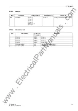
Configuration of the device functions are made via the DIGSI
®
software from your PC.
The procedure is described in detail in the SIPROTEC
®
4 System Description, Order
No. E50417-H1176-C151. Entry of password No. 7 (for setting modification) is re-
quired to modify configuration settings. Without the password, the settings may be
read, but may not be modified and transmitted to the device.
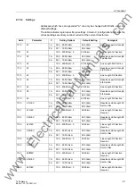
The function parameters, i.e. settings of function options, threshold values, etc., can
be entered via the keypad and display on the front of the device, or by means of a per-
sonal computer connected to the front or service interface of the device utilising the
DIGSI
®
software package. The level 5 password (individual parameters) is required.
2.1.1
Functional Scope
2.1.1.1
Configuration of the Functional Scope
The 7ST6 relay contains a series of protective and additional functions. The hardware
and firmware provided is designed for this scope of functions. In addition the
command functions can be matched to the system conditions. Individual functions can
be activated or deactivated during the configuration procedure. The interaction of
functions may also be modified.
The available protective and additional functions must be configured as
Enabled
or
Disabled
. For some functions a choice between several alternatives is possible, as
described below.
Functions configured as
Disabled
are not processed by the 7ST6. There are no in-
dications, and corresponding settings (functions, limit values) are not displayed during
setting.
Note
The functions and default settings available depend on the order variant of the device.
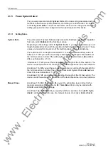
Enabling/disabling
of Functions
The protection functions can partly be enabled and disabled via different sources,
namely:
• Parameterisation (Para)
• Binary Input (BI)
• System Interface (SI)
A function is disabled as soon as it is switched off by one of the three sources. In order
to enable a function again, it must be switched on by all sources by which it had been
switched off.
The on or off state via binary input remains after a restart. After an initial start this state
is pre-defined as "on".
www
. ElectricalPartManuals
. com

