2 Functions
52
7ST6 Manual
E50417-G1176-C251-A3
2.2.4
Short-circuit Detection by Current and Voltage Angle Changes
In highly loaded, long overhead contact lines, when energizing with high loads or load
currents at the end of long supply zones, the load impedances can be as high as the
short-circuit impedances, so that an impedance comparison alone is no longer suffi-
cient.
In order to distinguish between such operating states and short-circuits, the tripping
characteristics Z2 and Z3 have two grading times which can be set independently.
The long grading time must be set to a value that is higher than the duration of a
startup procedure.
The short grading time is the delay time of the tripping characteristic from the grading
coordination chart.
In order to distinguish between short-circuits and energization, the 7ST6 devices are
equipped with a short-circuit detection that uses the criteria „
∆
I/
∆
t“ and „
∆
U/
∆
t“. In case
of an overload, the gradients of current (
∆
I/
∆
t) and voltage (
∆
U/
∆
t) are considerably
smaller than in case of a short-circuit. For the definition of these threshold values, the
load variations, which are a function of the distance between the feeding point and the
vehicle, must be taken into account.
You can set parameter
Rel. T2K
at address
1210
for zone 2 and
Rel. T3K
at
address
1220
for zone 3 to determine whether the criteria di/dt and du/dt are to be
combined via „AND“ or via „OR“. Refer to Figure 2-6.
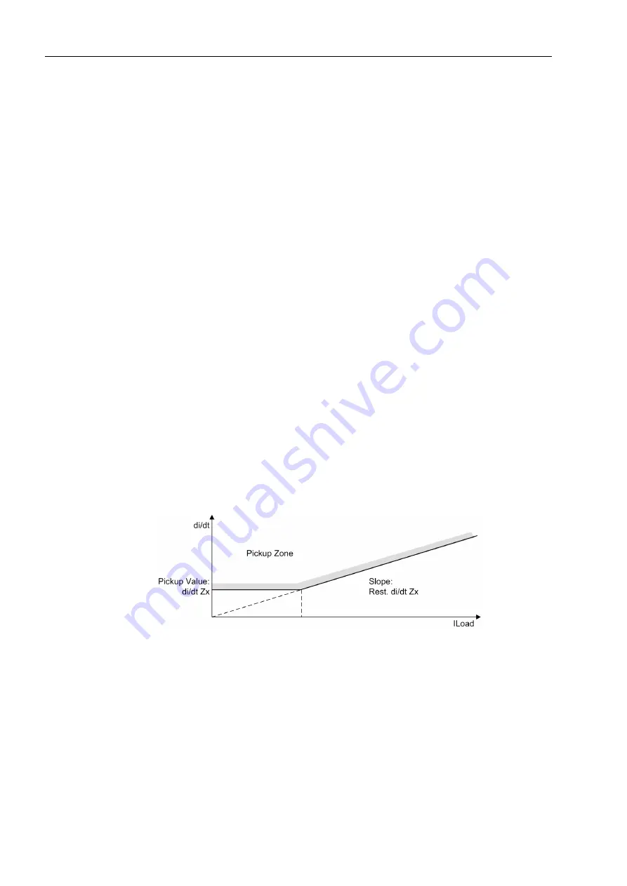
You can set the pickup sensitivity for di/dt against the present load current (energiza-
tion current) to ensure the sensitivity for short-circuit detection with small current
values and, simultaneously, prevent false tripping during energization with relatively
large current values. For zone 2 this is parameter
di/dt Z2
at address
1343
for the
initial value
Rest. di/dt Z2
at address
1211
for the slope in dependence on the
load current or
di/dt Z3
at address
1363
and
Rest. di/dt Z3
at
1221
for zone
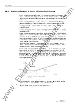
3. See following picture.
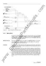
Figure 2-5
Tripping characteristic with restraint
If parameter
Rest. di/dt Z2
at address
1211
or
Rest. di/dt Z3
at address
1221
is set to 0, the settings for di/dt remain without restraint.
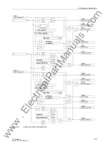
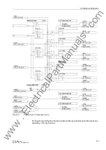
The figure below shows the short-circuit detection logic:
www
. ElectricalPartManuals
. com

