2 Functions
64
7ST6 Manual
E50417-G1176-C251-A3
Note
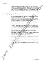
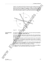
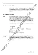
For all three distance zones to function correctly, the following conditions must imper-
atively be met for each characteristic:
γ
<
α
R < Z cos
α
R
≤
Z cos
γ
β
–
γ
≤
180
°
Polygonal Charac-
teristics
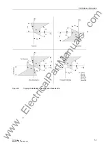
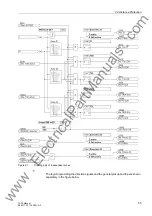
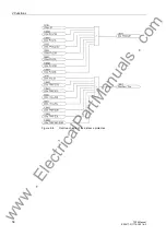
If the distance protection is to have impedance characteristics with polygonal charac-
teristic, set address
113
DISTANCE CURVE
=
Quadrilateral
.
For the description of the characteristic parameters in this section, general designa-
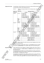
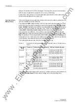
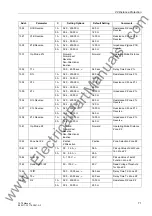
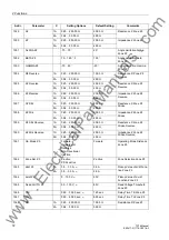
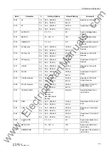
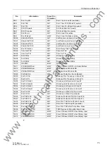
tions will be used. Table 2-2 shows the assignment of these designations to the actual
parameters of a zone.
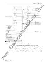
The reach of the characteristic is set with the parameter
X
. Here you set the balance
point reactance for the zone. For more information on setting the reach, please refer
to margin heading „Grading Coordination Chart“.
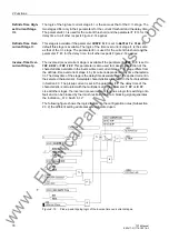
The load range is set with the parameters for the minimum load impedance
R
L
and the
spread angle of the load range
Alpha
(
α
). For more information on setting the load
range parameters, please refer to margin heading „Load Range“.
The safety margins of the directional characteristic are set in the parameters
Beta
(
β
)
and
Gamma
(
γ
). (see margin heading „Determination of Direction“).
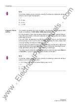
Note
For all three distance zones to function correctly, the following conditions must imper-
atively be met for each characteristic:
α
> 10
°
(if this is disregarded, spurious tripping may occur!)
γ
<
α
β
–
γ
≤
180
°
R
≤
X/tan
γ
www
. ElectricalPartManuals
. com

