2 Functions
106
7ST6 Manual
E50417-G1176-C251-A3
2.8.2
Setting Notes
General
The breaker failure protection can only operate if it has been set as
Enabled
during
configuration of the functional scope (address
139
BREAKER FAILURE
).
Circuit Breaker
Failure Protection
The breaker failure protection is switched
ON
or
OFF
at address
3901
FCT
BreakerFail
.
The current threshold
I> BF
(address
3902
) should be selected such that the protec-
tion will operate with the smallest expected short-circuit current. A setting of 10%
below the minimum fault current for which breaker failure protection must operate is
recommended. On the other hand, the value should not be set lower than necessary.
Single-stage
Breaker Failure
Protection
With single-stage operation, the adjacent circuit breakers (i.e. the breakers of the
busbar zone and, if applicable, the breaker at the remote end) are tripped after a delay
time
tBF2
(address
3905
) following initiation, should the fault not have been cleared
within this time.
The timer
tBF1
(address
3904
) is set to
∞
in this case, as it is not needed.
You can also use the first stage as the only one. In that case you have to set the time
tBF1
(address
3904
). Set
tBF2
(address
3905
) to
∞
or equal to
tBF1
(address
3904
). Be sure that the correct trip commands are assigned to the desired trip re-
lay(s).
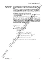
The delay times are determined from the maximum operating time of the feeder circuit
breaker, the reset time of the current detectors of the breaker failure protection, plus a
safety margin which allows for any tolerance of the delay timers. The time sequence
is illustrated in Figure 2-28. For sinusoidal currents, the dropout time can be assumed
to be less than 3/4 the cycle duration at rated frequency. If current transformer satura-
tion is anticipated, the time should be set to 1.5 ms.
Figure 2-28
Time sequence example for single-stage breaker failure protection
www
. ElectricalPartManuals
. com

